Building a wireless temperature sensor network, Part 4

This is part 4 of a series of blog posts documenting how I designed and built a multi-node wireless temperature sensor system.  Links to all of the posts in the series:

All hardware and software files for the project can be found in my GitHub repository.

The Base Station

Someone recently contacted me about this project and asked for more details about the base station that collects data from the remote sensors.  I didn’t bother to create a proper PCB for that part of the project, instead just soldering something together with perfboard, but I’m happy to share pictures and details about what I did.

The base station sits on top of a bookshelf, out of the way.  It’s powered from a USB adapter and all of my sensors are close enough that reception isn’t a problem.  I chose to use a nRF24L01+ radio that has an SMA antenna for greater range.  (It’s also a good idea to use that same radio on any remote sensors that are having trouble maintaining communication – it makes a big difference.)  The display isn’t critical because I push the data to a web site where I can view pretty graphs and such, but it’s useful for troubleshooting.  It continuously cycles through the temperature and supply voltage for each of the five remote sensors.  The number in the lower right is the number of times the base station displayed stale data for a sensor (because it failed to receive a recent reading).  That gives gives me a rough idea of whether I’ve got reception problems.  The count of 129 is pretty low considering that’s been accumulating since the last time our household power blinked (several weeks).

IMG_20180202_214444

The display module is a standard 16×2 character LCD display I bought from Ebay plus an I2C LCD backpack I bought from Banggood.  You could get something equivalent (though more expensive) from Sparkfun or Adafruit.  I covered the end of the LCD and an LED on the backpack with black tape to reduce distracting light bleed.

I designed the case in Fusion 360 and printed it on my 3D printer.  It’s somewhat specific to the prototyping board I used, but you can get the design files from my GitHub repository.

Here’s what the inside looks like:

00000IMG_00000_BURST20180202214848_COVER

The Circuit Board

I don’t have a schematic or a PCB layout for the circuit board but it’s pretty simple so a description should suffice.  The Particle Photon is powered from a micro-USB cable and we use the raw 5V pin on the Photon to power the display and the radio.  The display is 5V-native, so that’s fine.  The radio is actually 3.3V, and at first you might think you could power it from the Photon’s 3.3V pin (using the Photon’s onboard regulator), but after looking at the numbers I decided that the Photon’s 3.3V regulator wasn’t going to be able to power both the Photon itself and the radio (which can have high current spikes), so I actually ran the 5V line over to a separate 3.3V regulator (MCP1700-3302E/TO) and associated capacitors on the board and powered the radio that way.

IMG_20180202_215153

The code that runs on the Photon can be found in the GitHub repository.  The correct connections between the Photon and the radio can be found in comments at the top of the code file (MOSI, MISO, and SCK).

When I first started running this system I was forwarding events from the Particle cloud to my private Phant server, but SparkFun has since deprecated Phant so I switched to using a hosted virtual machine with ElasticSearch, Logstash, and Kibana (commonly known as the ELK stack).  You could also use Adafruit.io, ThingSpeak, Blynk, or whatever platform you prefer.

A Simple Telepresence Robot

I’m teaching a high school astronomy class this year (which I thoroughly enjoy, by the way!), and one of my students lives a couple hours away and uses Skype to attend the class sessions.  The class features a lot of group discussion and it’s kind of difficult for this student to follow what’s going on when all he can see on the screen is me.  I thought, “wouldn’t it be great if the student could rotate the camera around to see who’s talking?”

After contemplating that for a few minutes I realized that I could actually build something to enable that pretty quickly.  Most of my projects end up taking weeks of calendar time to complete (a couple hours here, a couple hours there, wait for an order to get shipped, etc.) but this one actually came together over the course of one weekend with parts I had on hand, just like I’ve always dreamed a project should go.

Here’s what the finished project looks like:

IMG_20171119_193623

Design

I usually run the Skype session with the student on my smartphone.  I wanted a device that would have these features:

  • Hold my phone upright in a secure fashion
  • Be able to rotate the phone 360 degrees
  • Allow the student to remotely control the rotation of the device
  • Be reasonably responsive to rotation commands
  • Operate silently so it doesn’t distract the class
  • Be powered from a standard USB port or charger.

I have a 3D printer so building the physical body wasn’t a problem.  I designed a sort of sleeve into which I could insert my phone, which would be attached to the shaft of a motor in the base of the device.

I had an Adafruit stepper motor on hand which was perfect for the job of rotating the phone.  It’s small, practically silent, can rotate 360 degrees, and runs on 5V.  I also had an L293D dual H-bridge motor driver IC suitable for driving this motor.

I’ve used the Particle Photon for a few previous projects and I really like it.  Fortunately I had an extra one on hand which made the remote control part really easy.  Particle has a really fantastic cloud platform that makes it trivial to invoke a function on the device via an HTTP call from anywhere on the internet.  That’s all I needed to build a link between a control web site and the robot.  There’s definitely some risk that Particle may go out of business some day and the cloud services will disappear, but for right now it’s hard to beat the speed with which you can build internet-enabled devices.  I think it’s an acceptable tradeoff for hobby projects like this.

Body

I designed the body of the telepresence robot in Fusion 360.  As an aside, I highly recommend Fusion 360 for designing physical objects where you might need to iterate on the proper physical size, because you can easily go back and change just the dimensions you need to tweak without rebuilding the whole object.  You can get a free hobbyist license as long as you’re not using it for profit.

The CAD files and STL files are available on Thingiverse.  I sized the sleeve for my Google Pixel phone, but if you download the Fusion 360 source file you can easily tweak the dimensions to fit whatever device you’re using.

The stepper motor is mounted inside the base using two 25mm M3 buttonhead screws.  It’s important to use screws with very shallow heads so that you get enough clearance for the phone sleeve to rotate above them.  The same two screws also hold the perfboard with the electronics.

The phone sleeve is attached directly to the motor shaft using a small set screw on the back.

IMG_20171119_193418

IMG_20171119_194528

Electronics

I used stripboard to solder the electronics together, but regular perfboard would work just as well.  I based the circuit on this Adafruit tutorial diagram, but using a Photon instead of an Arduino.  Power to the L293D comes from the VIN pin on the Photon which is powered directly from the USB port.  The layout needs to be kind of compact to fit in the base but it wasn’t hard to work out a good strategy after a little thought.

IMG_20171119_194751

Code

The code for the Photon can be found in the GitHub repository, but it’s pretty simple.  Here it is:

#include <Stepper.h>

int in1Pin = D0;
int in2Pin = D1;
int in3Pin = D2;
int in4Pin = D3;

Stepper motor(513, in1Pin, in2Pin, in3Pin, in4Pin);  

void setup() {
  pinMode(in1Pin, OUTPUT);
  pinMode(in2Pin, OUTPUT);
  pinMode(in3Pin, OUTPUT);
  pinMode(in4Pin, OUTPUT);

  motor.setSpeed(8);

   Particle.function("move", moveMotor);
   // This is saying that when we ask the cloud for the function "move", it will employ the function moveMotor() from this app.
}

void loop() {

}

int moveMotor(String command) {
    if (command=="left") {
        motor.step(50);
        return 1;
    }
    else if (command=="right") {
        motor.step(-50);
        return 0;
    }
    else {
        return -1;
    }
}

We’re using the Stepper library that’s available through the Particle cloud-based IDE, which has the same API as the stock Arduino stepper library.  We simply configure four output pins and then implement a function “moveMotor” that can be called remotely through the Particle cloud platform.  When the function is called it receives one string parameter that is the command we should execute, either “left” or “right”, then we just command the motor appropriately.

Web Site

My day job uses the Microsoft stack so the fastest route for me to get to a functional web site was to whip up something using ASP.NET Core.  If you’re more comfortable with Node or whatever, that’s fine too.  The full source code for the remote control web site can be found in the GitHub repository, but here are the important bits minus all the boilerplate code.

The javascript code that runs in the browser just invokes two server APIs:

<script>
    $(function() {
        $('#moveLeft').click(function() {
            $.post("api/moveleft");
        });
        $('#moveRight').click(function() {
            $.post("api/moveright");
        });
    });
</script>

And the code on the server side invokes the function on the Photon:

public class HomeController : Controller
{
    private HttpClient client = new HttpClient();
    private readonly IConfiguration configuration;

    public HomeController(IConfiguration configuration)
    {
        client.BaseAddress = new Uri($"https://api.particle.io/v1/devices/{configuration["device"]}/");
        this.configuration = configuration;
    }

    public IActionResult Index()
    {
        return View();
    }

    public IActionResult Error()
    {
        return View(new ErrorViewModel { RequestId = Activity.Current?.Id ?? HttpContext.TraceIdentifier });
    }

    [Route("api/moveleft")]
    public async Task MoveLeft()
    {
        await DoMove("left");
    }

    [Route("api/moveright")]
    public async Task MoveRight()
    {
        await DoMove("right");
    }

    private async Task DoMove(string direction)
    {
        var content = $"access_token={configuration["access_token"]}&args={direction}";
        await client.PostAsync("move", new StringContent(content, Encoding.UTF8, "application/x-www-form-urlencoded"));
    }
}

The call to the Particle cloud platform is done on the server, not the browser, so we can keep the device ID and access token secret.

Screen Shot 2017-11-19 at 9.33.55 PM

I hosted the web site in Azure but it’s using no special services so it can be hosted pretty much anywhere that can host ASP.NET Core apps.  Total response time, from clicking one of the buttons on the web site to having the device rotate the phone, is typically under one second, which is good enough for my purposes.

That’s all you need to an internet-enabled device up and running.  It doesn’t get much simpler than that!

Add a real-time clock to a Beaglebone Black

I’m using a Beaglebone Black to log some science data around the house.  My internet connection isn’t the most reliable in the world so I first cache the data locally on the BBB and upload it separately; this means I need to capture accurate timestamps for the data.  If the BBB reboots due to a power outage or something, I want the timestamps to be accurate even if the device can’t immediately sync the time from the internet, so I need a battery-backed real-time clock.

As I researched the proper way to do this, I discovered that there are a lot of articles and forum posts that discuss the topic but most of them had one or both of these problems:

  • They explained how to enable the RTC for the current session but not in a way that would survive reboots.
  • They gave instructions based on old or different OSes that weren’t valid for my device.

I finally put together something that I’m happy with so I’m documenting what I found.  None of this information is original discovery on my part but hopefully it’ll be in a form that’s useful to others.  However, it’s important to note that these instructions are for the Beaglebone Black running Debian 9 (Stretch), specifically “Linux beaglebone 4.4.91-ti-r133 #1 SMP Tue Oct 10 05:18:08 UTC 2017 armv7l GNU/Linux”.  They might be helpful for other devices or other Linux flavors but some things are likely to be different.

Hardware

I’m using a really cheap I2C-based DS1307 RTC that I ordered from China, called the Tiny RTC.  This device is available from a bunch of different sources but the design is exactly the same.  It’s actually a poorly-designed device but it’s dirt cheap and can be fixed with a bit of surgery.

Problems

The first problem is that the Tiny RTC is designed to trickle-charge a rechargeable LIR2032 battery, but a) the charging circuit isn’t very good and b) LIR2032 batteries aren’t widely available and tend to be of poor quality.  A regular CR2032 battery will last for years anyway, so it’s better to just disable the charging circuit.  Don’t put a non-rechargeable CR2032 into the device without first disabling the charging circuit; the battery may eventually explode if you do.

The second problem is that the Tiny RTC is designed as a 5V device but the BBB is a 3.3V device.  Fortunately the I2C bus lets us interoperate with 3.3V safely as long as we remove the pull-up resistors from the RTC.

The third problem is that the crystal oscillator is supposed to be soldered to the ground pad underneath it, according to the internet, but usually it’s not.  This can cause stability problems.

Another potential problem is that DS1307 chip doesn’t keep very good time and is sensitive to temperature variations, but since I planned to have the BBB regularly update the time on the RTC, that didn’t matter much to me.

Fixing the hardware

Here’s a picture of the board:

image

  • To disable the charging circuit, remove D1, R4, R5, R6, and short the R6 pads together.
  • To make the device compatible with the 3.3V BBB, remove R2 and R3.  If you plan to use the square wave output, remove R8 too.
  • Carefully solder the body of the crystal to the ground pad underneath it.  Do this rapidly so you don’t overheat the crystal.

Connecting to the Beaglebone

Refer to one of the many Beaglebone Black pinout diagrams available on the web.

  • Connect VCC to P9-05
  • Connect GND to P9-01
  • Connect SCL to P9-19
  • Connect SDA to P9-20

Note that the I2C pins on the BBB are for I2C-2.  This may be different on other devices, which would change many things below.

Test the hardware

You can test your work so far by running this command on the BBB:

i2cdetect -y -r 2

If the RTC is wired correctly and is communicating properly, you’ll see this output indicating that there’s a device at address 0x68:

image

Software

As I mentioned earlier, the challenge with setting up the RTC is to do it in a way that survives reboots and doesn’t require further manual intervention.  Most of the following instructions came from Mike Kazantsev’s excellent blog post with a few details filled in or tweaked for my specific environment.  He wrote some great technical explanations which I won’t attempt to duplicate here; if you want to know why the following steps work, read his post.

Add the RTC to the device tree

To make the kernel aware of the RTC device and to have it enabled at boot, we need to add it to the device tree.  Create a file named i2c2-rtc-ds1307.dts in your home folder with this content:

/dts-v1/;
/plugin/;

/* dtc -O dtb -o /lib/firmware/BB-RTC-02-00A0.dtbo -b0 i2c2-rtc-ds3231.dts */
/* bone_capemgr.enable_partno=BB-RTC-02 */
/* https://github.com/beagleboard/bb.org-overlays */

/ {
  compatible = "ti,beaglebone", "ti,beaglebone-black", "ti,beaglebone-green";
  part-number = "BB-RTC-02";
  version = "00A0";

  fragment@0 {
    target = ;

    __overlay__ {
      pinctrl-names = "default";
      pinctrl-0 = ;
      status = "okay";
      clock-frequency = ;
      #address-cells = ;
      #size-cells = ;

      rtc: rtc@68 {
        compatible = "dallas,ds1307";
        reg = ;
      };
    };
  };
};

Next, run this command to compile the overlay file and place the resulting overlay in your firmware directory:

sudo dtc -O dtb -o /lib/firmware/BB-RTC-02-00A0.dtbo -b0 i2c2-rtc-ds3231.dts

You may see a warning during compilation but it appears to be benign.

Now we need to tell the kernel to load that device overlay on boot.  Edit /boot/uEnv.txt and find the line that says, “###Custom Cape”.  Directly below that line, enable the example overlay line and make it look like this:

###Custom Cape
dtb_overlay=/lib/firmware/BB-RTC-02-00A0.dtbo

Now reboot and run this command:

ls -al /dev/rtc*

You should see this output:

image

Notice that we now have RTC0 and RTC1 devices.  RTC0 is the built-in hardware clock in the BBB but it has no battery backup.  RTC1 is the DS1307 that we connected to the BBB, so now we have two hardware clocks available.  We’re not done, though, because the /dev/rtc symlink is pointing to RTC0, not RTC1.

Make our RTC the default

We can add a udev rule that will symlink to our battery-backed RTC instead.  Create a new file named /etc/udev/rules.d/55-i2c-rtc.rules with this text:

SUBSYSTEM=="rtc", KERNEL=="rtc1", SYMLINK+="rtc", OPTIONS+="link_priority=10", TAG+="systemd"

Now reboot and run this command:

ls -al /dev/rtc*

You should see this output:

image

Now the /dev/rtc symlink points to our DS1307 RTC.

Set system time from RTC

Now we have our new RTC set up but the system time still won’t be set on boot.  The systemd-timesyncd service is responsible for time syncing in this build of Debian.  As it syncs the time from a time server it writes that time to disk.  If the device reboots and has no internet connection, systemd-timesyncd will see that the system time is unset and will load the last-synced time from disk and use that to set the system time (which wouldn’t be correct, but at least closer than a totally unset time).  We need to set the system time from our RTC before systemd-timesyncd checks it, and we can do that by creating a new systemd service.

Create a file named /etc/systemd/system/i2c-rtc.service with this text:

[Unit]
ConditionCapability=CAP_SYS_TIME
ConditionVirtualization=!container
DefaultDependencies=no
Wants=dev-rtc.device
After=dev-rtc.device
Before=systemd-timesyncd.service ntpd.service chrony.service

[Service]
Type=oneshot
CapabilityBoundingSet=CAP_SYS_TIME
PrivateTmp=yes
ProtectSystem=full
ProtectHome=yes
DeviceAllow=/dev/rtc rw
DevicePolicy=closed
ExecStart=/sbin/hwclock -f /dev/rtc --hctosys

[Install]
WantedBy=time-sync.target

Then run this command to enable the service to start on boot:

sudo systemctl enable i2c-rtc

Set the RTC from system time

As mentioned above, systemd-timesyncd will regularly correct the system time from a time server whenever you have an internet connection.  I thought that systemd-timesyncd would also update the default hardware clock at the same time, but it doesn’t.  Turns out it’s the kernel’s job to regularly copy the system time to the hardware clock, but the kernel actually targets /dev/rtc0 directly rather than using the /dev/rtc symlink, and this is set as a compilation option, not a runtime option, so it can’t be easily changed.  Instead of recompiling the kernel we’re just going to add another systemd service which will regularly update our RTC with the correct time.  This is particularly important since the DS1307 isn’t a very good clock and will drift significantly in only a few days.

First create a service file named /etc/systemd/system/systohc.service with this text:

[Unit]
ConditionCapability=CAP_SYS_TIME
ConditionVirtualization=!container
DefaultDependencies=no
Wants=dev-rtc.device
After=systemd-timesyncd.service

[Service]
Type=oneshot
CapabilityBoundingSet=CAP_SYS_TIME
PrivateTmp=yes
ProtectSystem=full
ProtectHome=yes
DeviceAllow=/dev/rtc rw
DevicePolicy=closed
ExecStart=/sbin/hwclock -f /dev/rtc --systohc

We want this service to run periodically to keep the hardware clock updated, so create a file named /etc/systemd/system/systohc.timer with this text:

[Unit]

[Timer]
OnUnitActiveSec=1h
OnBootSec=10s

[Install]
WantedBy=timers.target

Now enable the timer to start on boot with this command:

sudo systemctl enable systohc.timer

At this point we’re done with the software configuration, but don’t reboot yet because we want to do some testing.

Testing

To test that everything is working as expected, first set the DS1307 clock to some obviously incorrect date using this command:

sudo hwclock -f /dev/rtc1 –set –date=”2017-01-01 00:00:01″ –utc

Next, physically unplug any internet connection (wifi/ethernet) from the BBB and reboot.  When the BBB comes back up without an internet connection, running date at the command line should show you the incorrect date you set above.  This tells us that the date was loaded from the DS1307 on boot, which is what we want.

Now reconnect your internet connection, wait a minute or two, then check the system clock and both hardware clocks with this command:

date && sudo /sbin/hwclock -r -f /dev/rtc0 && sudo /sbin/hwclock -r -f /dev/rtc1

This will print out three date/time strings and they should all be the same (to within a few seconds since the commands to print each one are running sequentially).  This tells us that the system clock was synced from the time server and the updated time was also copied to both hardware clocks, which is what we want.

If you walk through these instructions and find errors or clarifications, leave a comment below.


Building a wireless temperature sensor network, Part 3

This is part 3 of a series of blog posts documenting how I designed and built a multi-node wireless temperature sensor system.  Links to all of the posts in the series:

All hardware and software files for the project can be found in my GitHub repository.

Programming the sensor module

Once you finish soldering a sensor module, the next thing you have to do is to set some configuration options and upload the firmware.  To do this, you’ll need an AVR programmer device of some kind.  We can’t use a simple USB cable like you can with an Arduino because a) we didn’t include USB components on the board and b) the processor doesn’t have any bootloader firmware installed.

There are a couple of different possible approaches for programming AVR processors.  If you don’t have a purpose-built programmer device but you do have an Arduino on hand, you can use the Arduino as your programmer.  There are also a variety of USB-based programmer devices you can buy; you can buy an inexpensive kit from Adafruit or I really like this one that’s sold by Femtocow on Tindie:

image

Once you have a programmer you need to connect it to the ICSP header on the sensor module.  You can either solder on headers and use a cable option of your choice or you can get this nice pogo-pin adapter, also from Femtocow:

image

Setting the fuses

Once you have your programming system set up, the first thing we need to do is set the “fuses” which are hardware level configuration options that control certain behaviors of the microprocessor.  In particular, we want to set the processor frequency to 8Mhz, tell the processor to preserve its EEPROM memory when it’s programmed, and set the brown-out detection feature to trigger at 2.7V.  If you’re using one of the USBtinyISP programmers I linked above you can use this command line to set the fuses:

avrdude -c usbtiny -p m328p -U lfuse:w:0xe2:m -U hfuse:w:0xd1:m -U efuse:w:0xfd:m

If you use a different kind of programmer you’ll probably have to use a different value for the –c parameter to tell avrdude which programmer you’re using.

The board core

Because we’re going to run the ATMEGA328P at 8 MHz, we need to use an Arduino board core that supports that clock speed.  The OSHLab Breadboard Arduino core works well for this; follow the installation instructions for adding it to your board manager, then install the core, then select the “ATmega328p (8mhz internal)” board from the list of boards.

Setting the ID

For reasons that will be clear a little later, the next thing we have to do is to give the sensor module a unique ID.  To do that, I use the id sketch in my GitHub repository.  (I’m not going to copy the source code here so that it won’t get out of date.)  Open the id.ino sketch in the Arduino IDE and set the nodeId variable to an integer between 1 and 9.  This value will become the ID of the sensor module (stored in EEPROM so it survives reboots) after it runs this sketch.  Once you’ve set an ID, upload the code to the sensor and you should see the onboard LED repeatedly blink a pattern that indicates the ID you set.  If you don’t see the LED blinking at all then either the programming didn’t complete successfully or you forgot to change the nodeId variable from its default value of 0.

The sensor module firmware

Finally we can upload the sensor module firmware sketch from GitHub.  Note that there are also two supporting files MCP9808.h and MCP9808.cpp in the same folder that you have to have in order to compile the sketch.  You can upload this sketch to the sensor module, overwriting the ID sketch, because the ID you programmed is saved in EEPROM memory.

Let’s look at some of the highlights of this code.  I’ll include relevant snippets here but remember that the version on GitHub is always the most up-to-date.

Setup

void setup(void)
{
  initializePins();
  loadNodeAddress();
  initializePeripherals();
}

When the processor first starts we do a few one-time things:

  1. Configure the GPIO pins (that aren’t otherwise configured by libraries) for our use.  Right now there’s only the LED output pin.
  2. Load the node address from EEPROM.  That function verifies that the ID it loaded is between 1 and 9 and if it’s not, it’ll blink the LED rapidly and continuously to indicate an error condition.
  3. Initialize the radio and temperature sensor.  The radio is configured to transmit at maximum power and the slowest bitrate in order to get decent range.  We don’t transmit very often or for long so this doesn’t hurt our battery life too badly.

Loop

Once everything is initialized we can start running the code that collects data and transmits it to the base station.  The high-level loop looks like this:

void loop(void)
{
  wakePeripherals();
  sendData();
  shutDownPeripherals();
  longSleep();
}

We wake up the peripherals from their sleep states, then we send the our collected data to the base station, then we put the peripherals back to sleep, then we put the processor itself to sleep.  Eight seconds later a timer wakes up the processor and we do the whole thing again, and this repeats forever.

Waking

Waking up the peripherals is interesting because the temperature sensor has some special considerations.  This is how we do it:

void wakePeripherals()
{
  // When we wake the sensor it takes time to do another conversion.
  // The time depends on the configured resolution (250ms for highest res.). We need to wait
  // until the sensor has had time to do another conversion after
  // waking or we'll just end up reading the previous conversion.
  sensor.wake();
  shortSleep();
  radio.powerUp();
}

When the MCP9808 temperature sensor first wakes up, it starts doing another reading but if you immediately ask it for a reading before it’s finished it’ll just give you the result of the last reading it took.  We need wait long enough to allow the sensor to finish taking its new reading, then we can ask it for the new data.  The code wakes up the sensor then puts the processor back to sleep for 288 milliseconds.  Once that time elapses then we can wake up the radio because we’re about to send out new data.

Sending data

Sending the data is pretty straightforward:

void sendData()
{
  int16_t buffer[2];
  buffer[0] = sensor.readTempC() * 16;
  buffer[1] = getBandgap();
  bool success = radio.write(buffer, sizeof(buffer));
  if (!success)
  {
    blinkIndicatorLed();
  }
}

We’re sending two 16-bit integers to the base station.  The first is the temperature in Celsius, encoded to an integer by multiplying it by 16 (the sensor measures temperature in 1/16 degree increments).  The second integer is the voltage that the processor is receiving from the voltage regulator.

I considered adding circuitry to allow the processor to sample the unregulated battery supply voltage, which would be a more interesting number, but at the time I was worried about input pin leakage current, so I decided to do something a little less cool and just have the processor measure its own supply voltage.  That will be really close to 3.0V constantly until the battery pack is close to exhausted and the regulator is forced out of regulation and the voltage starts to drop below 3V.  When that happens I know it’s time to change the battery.  In hindsight I think leakage current would be trivial and I should have at least included the ability to sample the raw voltage, so I’ll probably add that if I spin a new rev of the sensor module board.

By the way, I didn’t write the code that measures the processor’s power supply voltage; I got it from Nick Gammon’s blog (which is amazing and highly recommended).

If we’re successful in sending the data then nothing further happens.  We don’t want to blink an LED in this case because that’s just wasted power.  But if the transmit doesn’t succeed for some reason then we do blink the LED to indicate that something went wrong.  If the sensor is transmitting and being received correctly then this will hardly ever happen and if it’s not working correctly then battery life doesn’t really matter.

Sleeping

There’s some very specific code that needs to run in order to put the processor into its lowest-power sleep state, and once again I didn’t write it myself but instead got it from Nick Gammon’s blog, so go there to understand the mechanics of how it works.

Building a wireless temperature sensor network, Part 2

This is part 2 of a series of blog posts documenting how I designed and built a multi-node wireless temperature sensor system.  Links to all of the posts in the series:

All hardware and software files for the project can be found in my GitHub repository.

The schematic

In the previous post I talked about how and why I selected some of the major components that went into the sensors.  Now let’s cover the schematic and board design in more detail.  Important disclaimer: I’m not an expert at electrical engineering, I’m just a self-taught hobbyist.  I’m sure I made mistakes along the way.  If you see something in my design that’s wrong, feel free to leave a comment with constructive criticism!

Here’s the schematic for the sensor board (click for larger version):

image

Let’s walk through it piece by piece.

In the top left we have the power subsystem with the MCP1700 regulator that I picked out.  The MCP1700 needs 1µF capacitors on the input and output for stability, and general advice from people who have used the nRF24l01+ radio is that it benefits from a 100µF capacitor nearby to help satisfy current spikes as the radio turns on and off.  I was a little worried about leakage current through the electrolytic capacitor but in practice it appears to be insignificant.

In the top right we have the AVR ICSP header that we’ll use to program the ATMega328P.  In the lower left we have the pin headers for the nRF24L01+ radio to plug into.

The ATMega328P processer is in the bottom middle, obviously, and we have a decoupling capacitor on the power inputs and a pull-up resistor for the reset line.  I debated whether or not to include the reset line pull-up, because it’s not strictly necessary (the reset line has a weak internal pull-up built in), but decided to go ahead and do it in order to avoid potential problems.  I named and labeled the nets for the various data lines and didn’t run actual wires everywhere, which simplifies the diagram.  I went ahead and connected the IRQ line to the radio and the ALERT line to the MCP9808 even though I have no specific plans to use them right now, but they’ll be there if I change my mind.

Finally, in the lower right you will find the MCP9808 temperature sensor and its decoupling capacitor, plus an indicator LED which is very useful for diagnostics and displaying various bits of information about how the sensor module is operating.  I’ve made it a strong rule of thumb to always include at least one diagnostic LED on every board I make, whether I think I need one or not.  It always ends up saving my hide at some point.

The MCP9808 uses I2C for communication and I2C requires pull-up resistors in order to work correctly.  However, I really didn’t want to include external pull-up resistors on this board because a) that means more parts to place and b) the smaller the pull-up resistors are, the more current flows during I2C communication and we want to drive our current needs as low as possible.  I ended up just relying on the internal 20KΩ pull-ups in the ATMega328P and hoped that would be sufficient given the expected low capacitance of the data lines.  (Spoiler alert: it was, just barely.  More on that later.)

The board

Here’s the board layout (click for a larger version):

image

This is a two-layer board with a ground plane on the bottom and traces on the top.  I tried to minimize the number of traces on the bottom because they can break up the flow of return ground currents if poorly placed but I did have to use a few.  Making a good board layout is definitely an art form, and it probably helps if you’ve played a lot of Tetris.  For me, anyway, it’s largely a process of trial and error.  I start by grouping things that are connected to each other close together on the board, then I nudge things around and rotate parts trying to get the minimum number of crossed wires.  There are certain tricks you learn, like a resistor or capacitor gives you a free bridge to get from one side of a wire to the other, but mostly it’s a giant game of “what if?”

The power connector pads are sized for a standard terminal block but I pretty much ended up soldering the battery pack wires directly to the pads in order to save time and vertical space.

The ICSP header block can be populated with pins or left empty; I have a nice little pogo pin ICSP adapter that allows me to just touch the adapter to the ICSP pads on the board and quickly program the board.  (More about programming in a later post.)  The 100µF capacitor is a small 10V model that isn’t very tall.  The radio gets soldered directly into the 2×4 header in the middle of the board such that the body of the radio module is to the right of the header.  (As I was writing this I noticed that I didn’t do anything to mark that in the silkscreen, which is a mistake I should fix.)

The physical dimensions are roughly 42mm by 18mm, which is nice and small.  There’s one mounting hole and I rounded the corners of the board a bit to make it look nice.

I had the boards manufactured by OshPark (project shared here) and it cost me $5.75 for three of them, which is mind-blowing.  This really is a golden age for hobby electronics.  Everything worked on the first try, which I was pleased with.

image

image

Assembly

This was one of my first SMT projects and I learned a lot about SMT soldering techniques.  My purpose here is not to write a general SMT soldering tutorial because there are lots of excellent ones already available and I can’t improve on them, but here are some general tips that were particularly useful for me:

  1. Watch a lot of how-to videos on YouTube.  Don’t stop with just one; each video adds something unique and gives you a better overall picture of how it works.
  2. Liquid flux is an absolute must-have.  If you try to skip it, you’re going to have a bad time.  Trust me on this.
  3. Use a small pointy tip on your soldering iron for soldering small components like resistors and capacitors.  Apply a bit of solder to one pad, then slide the component onto the pad from the side while reflowing the solder, then do the other pad.  You might touch up the first pad with a bit more solder or use some liquid flux to get a great joint.
  4. A hoof tip for your soldering iron makes drag soldering the processor package a breeze (as long as you use lots of liquid flux!)
  5. Don’t stress too much about solder bridges when doing multi-pin packages.  They’re really easy to fix with solder braid if you mess up.
  6. Remember that the LED is a polarized part so orientation matters.  Different manufacturers do different things to mark the anode and/or cathode so there’s not just one reliable standard.  Carefully check the datasheet for your specific LED, or even better, if your multimeter has a transistor testing function, use that to light up the LED before you solder it and confirm for certain which direction the current flows through the part.
  7. I didn’t find solder paste and a hot air gun to be as effective as I expected.  It worked pretty well for small components but for multi-pin packages I had a hard time manually applying just the right amount of paste to prevent solder bridges.  A paste stencil would work better, I’m sure, but I didn’t bother with that.  Hand soldering on a small board like this is just fine.
  8. Practice, practice, practice.  You can buy inexpensive SMT soldering practice kits on EBay which allow you to solder to your heart’s content without worrying about destroying anything valuable.  Highly recommended.  The ones I bought on EBay were literally junk; they were just pads and parts and didn’t create a useful circuit.  That was fine – it gave me freedom to experiment without fear.  The ones I linked above appear to result in some kind of functioning circuit when complete which would be nice to tell you that you did it right, but then you have to worry more about messing up.

Here’s what the sensor module looks like when assembled (except for the radio):

image

And here is a shot with a bare board, an assembled board minus radio, and an assembled board with radio and attached to a battery pack:

image

I2C timing

I mentioned earlier that I left out the usual external pull-up resistors on the I2C data lines, hoping that the ATMega328P internal pull-ups would be sufficient.  After I assembled and programmed a sensor board I double-checked the bus timing with my oscilloscope and it turned out that I bet correctly, just barely.  The I2C spec says that for a standard rate data bus (100 kbit/s), the maximum rise time must be 1µs or less, where rise time is defined as the time it takes to go from 0.3VDD to 0.7VDD.  In our case VDD is 3V, so we’re looking for the time it takes for the rising edge to go from just under 1V to just over 2V.  It turns out that we’re squeaking in just under the limit:

NewFile0

That’s good enough for my own personal use.  If I were designing a commercial product I would want a bigger margin of safety there.

Self-heating

When I tested the sensor module before adding low-power sleep modes to the software, I found that the processor would actually heat up the board a bit with its dissipated power and skew the temperature readings upward by about 0.5°C.  It’s not a big effect but it’s a noticeable error with the MCP9808 that I’m using.  At first I thought I would need to redesign the board to include isolation slots to better shield the temperature sensor device from the rest of the board, but then I found that adding low-power sleeps between sensor readings reduced power dissipation enough that any remaining skew was insignificant, so that crisis was averted.

Power consumption

I’ll save an in-depth discussion of low-power sleep modes for the post on the sensor module software, but here’s the general idea.  The software puts the processor, the radio, and the temperature sensor to sleep and sets a timer for eight seconds.  When the timer fires, the processor wakes up, wakes up the radio and temperature sensor, gets the current reading, and sends the data.  It then puts everything back to sleep for another eight seconds.

Here is the best result I was able to achieve during the eight-second sleep time (measured with an EEVBlog µCurrent):

image

The µCurrent was set to the µA range, so every µA of current across the input terminals produces 1 mV of voltage across the output terminals.  As you can see, I’m using 6.3 µA of current during sleep, which is great.

When the system wakes up to take a measurement and send data it uses more current, of course.  To characterize that transient behavior I hooked up the µCurrent to my oscilloscope.  I switched the µCurrent to the mA range, but the active current draw (and thus voltage signal) turned out to be right down in the noise for the oscilloscope.  I heavily filtered the signal and was able to get an idea of the duration (about 12 ms) and current draw (a quick spike to 23 mA then steady at ~14 mA for the rest of the wake period).

NewFile1

14 mA is a lot of current, relatively speaking, but the length of time we’re drawing that kind of current is quite short.  If I did my math right, it averages out to about an extra 1.5 µA over the course of an eight-second cycle, so our average current draw over time is approximately 8 µA.  The self-discharge rate of an AA battery is also roughly 8 uA so the life of our batteries is going to be 50% of what it would be if they were just sitting on a shelf, which is to say that the expected lifespan of these sensor modules is well over a year, at least.  We’ll see if it actually turns out that way in practice but I’ve had three sensor modules running continuously since March and their batteries are still going strong so things are on the right track.

Current measurement side notes

Characterizing current draw for a low-power device can be tricky because of the dynamic range of the current draw over time.  In my wireless sensor, the difference between the sleep state and the peak active state is three orders of magnitude (~3,650x).  The µCurrent is a great device but its measurement ranges cover nine orders of magnitude (1 nA to more than one amp) and compromises must be made.  The maximum voltage output of the µCurrent is 1.4V so you can measure up to about 1.4mA on the µA range for example (giving an output of 1.4V) then you have to switch to the mA range (giving an output of only 1.4mV).  A 1.4mV signal is going to be completely lost in noise on an oscilloscope so now you’re stuck in a very awkward position if you want to measure fast transients.  I don’t know of a great solution for this problem; maybe a secondary amplifier to boost the signal into a range that the oscilloscope is happy with?

Also, doing extremely low-current measurements is really tricky because external noise can easily swamp the signal you’re trying to measure even if it’s supposedly at a good level for your test instrument.  At the nA range, every test lead is an antenna pulling in all kinds of EMI and you have to be very careful how you set up your experiment.  It’s super-easy to get nothing but nonsense from your instrument if you do it wrong.

I think that’s all I wanted to cover for the sensor module hardware.  Next time we’ll talk about the software that makes it do useful stuff.

Building a wireless temperature sensor network, Part 1

Over the past few months I’ve been working on an electronics project that has taught me a lot.  Because I’ve benefited so much from the internet community in the process of my own learning, I’ll document the project here in hopes that it will help other people who want to learn.

This is part 1 of a series of blog posts documenting how I designed and built a multi-node wireless temperature sensor system.  Links to all of the posts in the series:

All hardware and software files for the project can be found in my GitHub repository.

The project

Because I’m a science geek, I’ve always thought it would be interesting to have a set of low-cost wireless temperature sensors that would allow me to monitor temperatures in a variety of locations around my property in real time, graph that data in real time, and hook up the output of certain sensors to physical display devices.  Of course you can purchase a wide variety of commercial wireless temperature sensors but they mostly have the drawback of being:

  • Expensive
  • Proprietary (not easy to log the collected data to the internet)
  • Not scalable to multiple sensor modules.

You can sometimes fix the last two problems by making the first problem worse (i.e. really expensive units often support internet data logging and many sensors) but I didn’t want to sink a lot of cash into this project, and anyway building my own is half the fun.

I thought about it off and on for quite a while and came up with this list of requirements:

  1. The overall system with one sensor module should cost less than $40 to build.
  2. The system should support at least 5 sensor modules.
  3. Each additional sensor module should cost less than $10 to build.
  4. The sensors should be wireless and battery powered so they can be placed anywhere.
  5. The battery life of the sensors should be at least one year.
  6. The sensors should be physically small so they can fit in tight spaces and are unobtrusive.
  7. There should be a central display device that shows the current reading of all sensors.  This display device doesn’t have to be battery powered (i.e. wall power will be available).
  8. The system should not require a PC or other expensive computing device.
  9. All sensor readings should be logged to my private Phant server on the internet.
  10. I should be able to tell when the battery on any sensor is getting low.

There might be a little retroactive tweaking of the requirements going on (since I’ve already mostly-finished the project) but that’s pretty much what I had in mind from the beginning.

General system design

Given those requirements, I started thinking about the general design of the system.

Base station

Working backwards, I knew that the logging repository for my collected data would be on the internet so I needed the system to be internet connected.  Of course I have a home WiFi network but WiFi is very power-intensive so the sensor modules can’t use it directly, therefore I needed a base station that was WiFi-capable and HTTP-capable.  It also needed to be inexpensive and to be able to drive some sort of display.  The display didn’t have to be anything fancy; a 16×2 character LCD screen would be sufficient for my purpose.

I’ve previously done a couple of other projects with the Particle Photon and it’s a great choice for this kind of problem.  It’s $20, it has a decent amount of memory and CPU resources, it supports WiFi, it has a great library for easy internet connectivity, and it has GPIO pins that allows me to hook up an LCD screen, a radio, buttons and anything else that I need for the base station.  I could have used a Raspberry Pi or Beaglebone Black for this purpose as well but they’re more expensive and have far more features than I really need for this project.  The Photon is the perfect balance of simplicity, power, and cost for a project like this.

Radios

Ok, I have a base station.  How does it communicate with the sensor modules?  I needed a low-cost and low-power radio device that I could use to send small data packets.  There are lots of interesting products in this space, for example XBee, but they tend to be more expensive than I was hoping for.  I did a bit of research and discovered the nRF24L01+ chipset which is used by many very inexpensive radio modules available on Amazon and EBay.  There’s good software library support for this module on multiple platforms and it’s very easy to understand and use.  The range isn’t great, especially for the modules that use PCB-based antennas, but they’re pretty power-efficient and at a cost of just a dollar or two per radio, it’s hard to beat.  (Update: you can also buy versions of the nRF24L01+ radio that have an SMA antenna instead of a PCB antenna, which will significantly increase range.)

2pcs nRF24L01+ 2.4GHz Wireless Transceiver in Antistatic Foam Arduino Compatible

Side note: If you want to try using the nRF24L01+ radio on its own or prototype with it for your other projects, check out this breadboard adapter for the nRF24L01+ that I designed to make it easier to experiment with.  It separates the rows of pins so you can plug it into a breadboard and also includes an on-board 100uF capacitor and on-board 3.3V regulator so you can use it with a 5V device like the Arduino Uno.  The nRF24L01+ requires 3.3V power but is 5V tolerant on its I/O pins so you don’t need a level shifter.

Processor

Now we can turn our attention to the sensor modules themselves, which is the most interesting part of this project from an electronics perspective.  I didn’t find anything on the market that did exactly what I wanted to do so I decided to design my own sensors from scratch (which, again, is half the fun).

I’m pretty comfortable with the Arduino ecosystem and I’ve already done several projects using a bare ATMega328P chip which is the processor on an Arduino Uno.  The ATMega328P can be programmed to operate in a low-power mode that doesn’t draw much current and it has more than enough compute resources to drive the sensor module, since all it really needs to do is query a hardware temperature sensor device and then send that data to the radio module.  Also, it’s available in surface-mount packages that would allow me to minimize the size of the circuit board.

image

Temperature sensor

There are few commonly-used temperature sensors for hobbyists, including the TMP36 and the DS18B20, but there are other sensors on the market which have better resolution and accuracy ratings and since I was designing this thing from scratch, I figured I might as well go all the way so I chose the MCP9808 which has a typical accuracy of 0.25°C and a maximum resolution of 0.0625°C.  It’s not as popular in the hobby space because it’s only available in surface-mount packages, but I wanted to do an SMD board design for this project anyway and there are Arduino driver libraries that make communication easy.

Batteries and voltage regulator

I wanted the sensor modules to be able to run for a year or more on a single set of batteries because I’m lazy and don’t want to be changing batteries all the time.  That implied two things: a) I need to use batteries that have low self-discharge rates and b) the sensor board needs to be able to operate from the maximum voltage supplied by fresh batteries all the way down to the minimum voltage supplied by exhausted batteries.

I initially considered using a rechargeable LiPo battery but lithium batteries typically don’t have very good self-discharge rates.  That is, a typical LiPo battery will lose about 10% of its charge per month just sitting there while a modern rechargeable AA battery like the Enerloop brand will lose about 0.3% per month.  In addition, my sensors don’t have any high-current needs that LiPos are well-suited for, so rechargeable AAs definitely made the most sense.

Looking at the various components I had already picked out, each part had its own voltage operating range but everything seemed to overlap nicely in the 2.7V – 3V range.  AA batteries hit about 0.9V when they’re almost all the way drained, so three of them in series would allow me to use practically all of the energy in a set of batteries before shutting down.  However, a fresh AA cell can deliver up to 1.6V, or 4.8V for three of them in series, which is more than the absolute maximum voltage of the nRF24L01+ radio (3.6V).  So clearly we need a voltage regulator.

Now, we could just drop a basic 3.3V regulator like the LD1117V33 into the circuit but that device has a few major problems for our application.  One, it has a voltage drop of ~1.1V, which means that in order to supply 3.3V it has to be fed at least 4.4V, which means the batteries would have to be practically brand new.  Two, even if we did have enough source voltage range (maybe by adding more AA cells), the quiescent current of that device is around 5 mA.  That means that even if we’re drawing no current at all into the rest of the circuit, the regulator itself will burn 5 mA just sitting there, and there’s no way we’re going to last a year with that kind of power drain.

I did some research and found the MCP1700 which is great regulator for my particular application.  It can be ordered in a variety of low-power output voltages, including 3.0V which is what I want.  The quiescent current is only 1.8 µA, which is crazy low, and the dropout voltage at the tiny current levels we’re going to operating at is roughly 25mV or less, which is also crazy low. Finally, it’s available in a surface-mount SOT-23 package which is great.  This part can only deliver 250 mA of output current but we’re not going to draw anywhere near that anyway, so I don’t care.

Stay tuned

That’s enough words to start with!  In the next post I’ll go into detail on how I designed and built the sensor board.

Hardware Hacking For Software Developers

I studied Software Engineering in college.  Most of the major classes were about various software topics, of course, but I was also required to take a couple of hardware/electronics classes where we soldered together transistors and logic gates and such things.  At the time I didn’t particularly enjoy it – software was logical and always worked the same way while hardware was messy and was constantly not working due to bad solder joints or “letting the magic smoke out” or what have you.  Very frustrating.

Fast forward 20 years and I’ve been doing the software thing for a long time.  I’m still passionate about programming and love what I do but I was looking for something new to spend hobby time on.  Preferably something relatively cheap, that I could combine with my interest in amateur science, and that would bring me back to a state of “beginner mind” where I could have fun learning again.  I decided to turn my attention back to the world of electronics to see if it would “take” any better the second time around.

It turns out that the world of hobby electronics is currently in a golden age and it’s amazing!  Between the ocean of free information available on the internet, the fantastic companies that cater to hobbyists, and the wide availability of low-cost, high-quality tools and equipment, there’s never been a better time to get into the hobby.

So you want to hack some hardware?

I’ve been working with this new hobby for about a year now and while I’m certainly no expert, I thought I’d share the results of some of my research to maybe save others some time and to “give back” to the internet community that’s helped me so much.  This post will be a high-level overview of some of the interesting directions in which one can explore, and resources I’ve found to be the most useful.  It’s adapted from a talk I did for the South Sound Developers User Group earlier this year.

As a software developer, it’s pretty easy to ease into the electronics field, starting with high-level things that are comfortably familiar and working your way down to raw electronics with transistors and opamps and stuff.  There are a huge array of options available and I can’t possibly cover them all, so I’ll just describe the journey I took and the results I got.

Microprocessor boards

Probably the easiest place to start is with one of the many types of small microprocessor boards available today.  Two of the most popular right now are the Raspberry Pi and the BeagleBone Black.  These are full self-contained computers on a single small board, usually running some kind of Linux-based OS on an ARM processor.  The fact that they’re small and low-power is nice, I guess, but the really interesting thing about them is that they usually include a number of general purpose I/O pins that you can hook up to external electronic circuits in order to control them or to acquire data from them.  These GPIO pins aren’t tied to any kind of complex protocol like USB or even serial; instead you can directly set each output pin on or off, or check the current state of each input pin.  This allows you to do something trivial like blink an LED on and off, or things that are far more complex.

product_detail_black_sm[1]

One of my first electronics purchases was a BeagleBone Black and I’m very happy with it.  It has enough processing power to run Linux, lets me program in my language of choice (Python, Javascript, C, etc.), and is easy to hook up to my home network and thus to the internet.  It has a wide array of GPIO pins, both digital and analog, and also has USB and HDMI ports to connect a monitor and keyboard if desired (though I usually just SSH into it).

I bought the BeagleBone Black along with an inexpensive beginner’s electronics parts kit (see below) and had a lot of fun wiring up LEDs, switches, and other components on a breadboard and connecting them to the BeagleBone.  I refreshed my memory about the basics of simple electronic circuits but soon found myself wanting to go a bit more low-level.  After all, the BeagleBone Black wasn’t too much different than the laptop I work on every day and I wanted something a little more different than my day job.

Microcontroller boards

Having the power of a full Linux OS is nice but I wanted to get a little closer to the hardware.  I picked up an Arduino Uno, which is a microcontroller board.  Like the BeagleBone Black, the Arduino has several digital and analog GPIO pins which which to interface with external electronic circuits.  However, unlike microprocessor boards, the hardware resources available on a microcontroller board are much more limited.  The Arduino Uno has only 32 KB of storage and 2 KB of RAM, so you aren’t going to be running Linux on this thing.  In fact, you don’t have any kind of OS available at all.

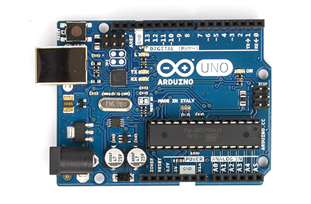
Instead, you write self-contained programs which are uploaded to the board over USB and get directly executed by the microcontroller.  There’s no OS to get in the way; your program is the only code running and you have full control over and responsibility for everything that happens.  This is simultaneously limiting (no networking, video, or keyboard/mouse supported out of the box) and also liberating because your code executes predictably in real time without being preempted by other threads or processes.  This allows you to do things that require precise timing control such as operating servo motors for robotics projects.

It’s still pretty easy to program, though, because there’s an IDE and libraries available to help you with the dirty work.  Using the Arduino IDE on your computer, you write code in Arduino-flavored C++, cross-compile it for the Atmel AVR ATmega328 microcontroller on the board, and upload the resulting binary via a USB cable.

The Arduino is an extremely popular hobbyist board and there are a ridiculous number of tutorials, project descriptions, and forums to give you advice and inspiration.

Bare microcontrollers

The Atmel AVR ATmega328 microcontroller that runs the Arduino is not a particularly modern chip but it’s well understood and a huge community has grown up around it.  It’s quite inexpensive and easy to experiment with.  It turns out that it’s not particularly difficult to buy the chip all by itself, whack it and a couple of other cheap components onto a breadboard, and make your own homebrew Arduino.

image

Furthermore, the AVR line of microcontrollers includes chips that are both larger and smaller than the ATmega328 used in the Arduino but they’re all software-compatible, so you can choose precisely the minimum amount of silicon you need to build your project.  Using a bare chip in your project is a little more inconvenient than using an Arduino board but if you’re soldering stuff together anyway and you need it to be small, including an AVR chip directly in your circuit is the way to go.  Besides which, soldering bare chips makes you feel like you’re actually doing electronics!

Analog circuits

So far, everything we’ve discussed is primarily centered around writing code for a processor of some kind with some ancillary circuitry thrown in.  That’s a great way for a software developer to start but since my goal was to do something completely new, I needed to break out of the programming paradigm completely.

3714224615_90908a2353_z

It turns out that there are all kinds of things you can do with just analog components and a breadboard; no digital code required.  That was a revelation to me.  I mean, duh, of course I knew that, but after 20 years as a software developer I had some pretty deep-seated biases toward digital logic.  The first time I wired up a 555 analog timer chip to blink an LED and was able to change the rate of the blinking by merely swapping one resistor value for another, I realized that this was the “totally new” thing I’d been looking for.  I still do a lot of stuff with microcontrollers in my projects but it’s become a game of sorts to see how little code I can get away with, with zero being the ideal.  I’ve learned a lot about low-level electronics over the past year and I’ve barely scratched the surface.  I’m having a ton of fun, though!

Tools and resources

There are several tools I’ve purchased and valuable resources I’ve found that have helped me in my learning.  Below are some of the highlights.  This is by no means an exhaustive list and there may well be even better choices out there, but these are the things that I found valuable to me.

Hobbyist stores and distributors

There are a lot of online stores out there that offer all kinds of electronics components.  Some of them are good, a lot of them are sketchy.  Adafruit and Sparkfun are two companies that I can highly recommend.  They both carry high-quality components suitable for hobbyists, both carry lots of custom-designed components and boards to make building projects easy, and both publish a wide range of tutorials and project guides to help you use what you buy.  Their prices aren’t the cheapest you can find, but I strongly recommend sending your business to these companies because they stand behind their products and are actively building up the hobbyist community.  Just beware – browsing either one of those websites can be hazardous to your wallet.  So much awesome stuff!

If you’re shopping for unusual components, or components with very specific characteristics, or a large quantity of components, then you might want to try a large distributor house.  Mouser and Digikey are both well-regarded, reliable distributors that stock literally hundreds of thousands of different electronics parts.  If you need it, they probably have it.  Your biggest problem will be deciding exactly what you want to order.  You want a capacitor?  Mouser has 346,459 different kinds.  You’ll need to get proficient with their catalog search tools and know how to read datasheets because there’s no handholding here.

Also be aware that these distributors focus on large-volume orders.  They’re willing to sell you singles of most things but it’s not going to be particularly cheap.  You need to buy in reasonable quantities to get discounts.

Electronic parts and kits

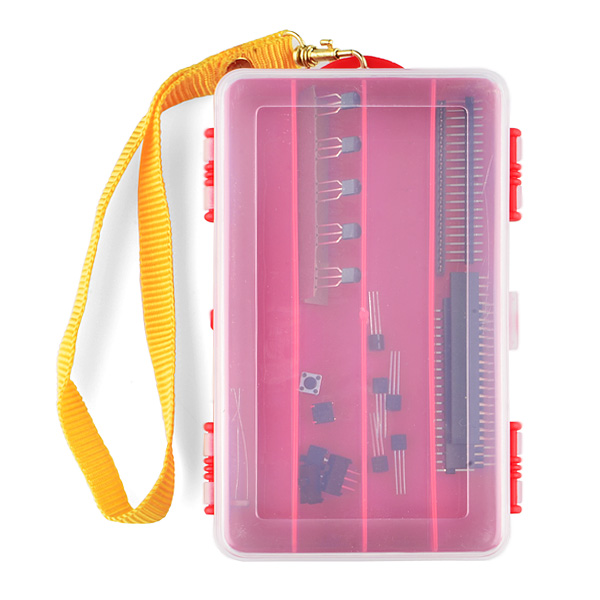
To get started, I purchased a couple of breadboards, the Beginner Parts Kit, and the Resistor Kit from Sparkfun.  These are nice little kits that gives you a few of each of the most commonly-used components for beginning electronics projects.  This is a great way to get jumpstarted with building simple electronics circuits to connect to your BeagleBone Black or Arduino.  There’s lots of other options out there, of course, but I was happy with these.

When it was time to build a larger parts inventory, I was pleased with kits put together by Joe Knows Electronics that I ordered from Amazon.  I have the resistor kit, capacitor kit, semiconductor kit, and LED kit and they’ll keep me going for a good long time.

Multimeter

EX330 - 12 Function Mini MultiMeter + Non-Contact Voltage Detector

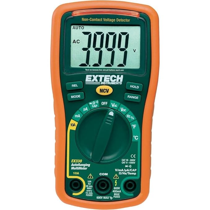
A good multimeter is the first tool you should invest in as you pursue a hobby in electronics.  A good choice is the Extech EX330.  It’s reliable, has a good set of features, and is reasonably priced.

Soldering Station

Aoyue 9378 60 Watt Programmable Digital Soldering Station - ESD Safe, includes 10 tips, C/F switchable, Configurable Iron Holder, Spare Heating Element,100-130V

I learned a long time ago that if you’re going to invest in equipment for a hobby, you should buy quality stuff that actually works well.  There are lots of low-end soldering irons out there but most of them will simply cause you to be frustrated and maybe give up on the whole thing altogether.  After some research I purchased an Aoyue 9378 soldering station that I’ve been happy with.  There are several other good choices in this price range, too, but this one seemed to be recommended a lot.

Power supply

Mastech HY3005F-3Triple Linear DC Power Supply, 30V, 5A

One of the first “from scratch” projects you can build is a breadboard power supply to feed 3.3V or 5V power to your circuits.  It’s fun and satisfying to build your own tools.  However, when your needs expand to higher voltages or high current, and you need features like current-limiting to avoid blowing stuff up, then it’s time to get a real power supply.  I purchased a Mastech HY3005F-3 power supply.  It’s solid and reasonably priced.  It’s not programmable or anything (that stuff is found in higher price levels) but it gets the job done.

Oscilloscope

An oscilloscope is an incredibly useful tool for understanding and diagnosing non-trivial circuits.  Where a multimeter will tell you the voltage at a particular contact point right now, an oscilloscope allows you to see how it varies over time.  This is the sort of tool where it’s hard to imagine how it would be useful until the first time you actually use one, then wonder how you ever got along without one.  I chose the Rigol DS1102E and like it a lot.  There are fancier ones available for more money but this one seems to do everything I need for now.

Blogs

image

There are a ton of great resources for the electronics hobbyist on the internet and I won’t attempt to list them all.  One of them particularly stands out in terms of being both instructive and entertaining, though: EEVBlog.  Dave has hundreds of video episodes covering everything from electronics fundamentals and theory to teardowns of various pieces of equipment to live repair jobs.  I learned a tremendous amount just from watching how he uses his tools.  I recommend starting with episode #168: How To Set Up An Electronics Lab.

Circuit simulation

Sometimes you don’t want to take the time to actually build a circuit on a breadboard to see if it will work.  Or maybe you don’t have the correct parts at hand, or you’re afraid you might screw it up and blow up a component, or whatever.  In such cases it’s very useful to be able to simulate your circuit ideas in software first before you commit to the real thing.  There are software packages you can download for this purpose, but I’ve been pleased with CircuitLab.com.  It’s not free but the user interface is very intuitive and it’s helped me better understand how transistors and opamps work because I can quickly set up various scenarios and see instantaneous voltage and current values, or chart them over time.

Go forth and learn!

So that’s a lot of high-level information about how to get started with an electronics hobby.  You’ll notice that I didn’t discuss the “how-to” on anything, but a few web searches should turn up lots of resources for any particular topic that catches your interest.  The most important thing is to actually do something.  Start small, understand and master what you’ve purchased, then move on to the next step.  Personally, I’ve found it to be very rewarding and I hope you will too.

Reality-based Interviewing

The job market for senior software developers is very hot right now (as of early 2014), at least in Seattle.  I know of several companies in the area that have aggressive hiring plans for the next 12 months, often with the goal of doubling or tripling in size.  Most of these companies intend to hire mostly or exclusively senior developers because their long-term productivity is so much greater than the typical junior or just-out-of-school developer.  I find it remarkable, however, that these same companies often don’t have an interviewing strategy that’s designed to select the kind of candidates they’re actually looking for.

A fairly typical interview strategy consists of an introductory conversation focused on cultural fit and soft skills.  This is sometimes a panel interview but is relatively short.  The vast majority of time is spent in one-on-one sessions doing whiteboard algorithm coding problems.  These coding problems are typically small enough that there’s a possibility of completing them in an hour but also obscure or tricky enough that most candidates have a significant likelihood of messing up or not finishing.  The candidate has to understand the description of the problem, construct an algorithm, and write code for the algorithm on a whiteboard, all the while talking out loud to reveal his or her thinking process.  Google is the most famous for this style of interviewing, but Microsoft has been doing it for decades as well and the whole rest of the industry has pretty much followed the lead of the big dogs.

Broken By Design

So what’s the problem?  Well, according to Laszlo Bock, senior vice president of people operations at Google, it simply doesn’t work:

Years ago, we did a study to determine whether anyone at Google is particularly good at hiring. We looked at tens of thousands of interviews, and everyone who had done the interviews and what they scored the candidate, and how that person ultimately performed in their job. We found zero relationship. It’s a complete random mess, except for one guy who was highly predictive because he only interviewed people for a very specialized area, where he happened to be the world’s leading expert.

Why doesn’t it work?  The short answer is because what we ask people to do in interviews often has very little relationship to what we actually expect them to do on the job.  Maria Konnikova offers a longer answer in a New Yorker article:

The major problem with most attempts to predict a specific outcome, such as interviews, is decontextualization: the attempt takes place in a generalized environment, as opposed to the context in which a behavior or trait naturally occurs. Google’s brainteasers measure how good people are at quickly coming up with a clever, plausible-seeming solution to an abstract problem under pressure. But employees don’t experience this particular type of pressure on the job. What the interviewee faces, instead, is the objective of a stressful, artificial interview setting: to make an impression that speaks to her qualifications in a limited time, within the narrow parameters set by the interviewer. What’s more, the candidate is asked to handle an abstracted “gotcha” situation, where thinking quickly is often more important than thinking well. Instead of determining how someone will perform on relevant tasks, the interviewer measures how the candidate will handle a brainteaser during an interview, and not much more.

(Edit: she’s referring to non-coding brainteaser questions here, but many “coding” interview questions also fall in to the toy brainteaser category.)

Why is it that we set out with the intent of hiring senior developers who are valuable specifically for their maturity, experience, and enormous depth of knowledge about how to build large software systems and end up evaluating them strictly on small-scale tactical coding exercises that would look right at home in any undergraduate homework set?  Why do we evaluate them in an artificial environment with horribly artificial tools?  Why is it so completely out of context?

Don’t get me wrong – it’s obviously important that the people we hire be intelligent, logical, and competent at tactical coding.  But tactical coding is only one part of what makes a great senior developer.  There are many vital technical skills that we don’t often explore.  When our interviews are artificial and one-dimensional we end up with poor-quality teams, because a healthy software team needs a variety of people with various strengths.  Selecting for only one narrow type of skill, even if it’s a useful skill, is a mistake.  There has to be a way to create more relevance between our interview questions and the palette of skills we’re actually looking for.

Focus on Reality

What is it that we do all day at our jobs?  We should take whatever that is and transfer it as directly as we possibly can into an interview setting.  If we’re not doing it all day every day we shouldn’t ask our candidates to do it either.

Let’s start with the venerable whiteboard: when was the last time any of us wrote more than a couple of lines of syntactically-correct code on a whiteboard outside of an interview setting?  That’s not a job skill we value, so don’t make candidates do it.  Give them a laptop to use, or better yet, allow them to bring their own, if they have one, so they have a familiar programming environment to work with.

Next, what kind of problems do we solve?  A few of us regularly invent brand new algorithmic concepts, be it in computer vision, artificial intelligence, or other “hard computer science” fields.  But let’s be honest – the vast majority of us spend our time doing more prosaic things.  We just move data from point A to point B, transforming it along the way, and hopefully without mangling it, losing parts of it, or going offline during the process.  That’s pretty much it.  Our success is measured in our ability to take old, crappy code, modify it to perform some additional business function, and (if we’re really talented) leave it in a slightly less old and slightly less crappy state than we found it.  Most of us will never invent any new algorithm from first principles that’s worth publishing in a journal.

This is the reality of day-to-day software development.  Small-scale tactical coding skills are expected to measure up to a certain consistent bar, but the key differentiator is the ability to write self-documenting, maintainable, bug-free code, and to design architectural systems that don’t force a wholesale rewrite every three years.  Clever binary tree algorithms we can get from the internet; a clean supple codebase depends directly on the quality of the developers we hire and ultimately determines whether our companies succeed or fail.

How do those skills translate into an interview setting?  I think a refactoring exercise is a great way to accomplish this.  Give the candidate a piece of code that works correctly at the moment but is ugly and/or fragile, then ask them to extend the behavior of the code with an additional feature.  The new feature should be small, even trivial (this isn’t an algorithm test) because the challenge for the candidate is to add the new behavior without introducing any regression bugs and also leaving the code in a much better state than in which it started.  I’m sure we all have lots of great messes we can pull straight from our production codebases (don’t lie, you know you do!), but if you want an example, take a look at the Gilded Rose Kata (originally in C# but available in several other languages as well).

A few companies have expanded even further on this idea of reality-based interviewing.  They’ve done things like dropping the candidate into the team room for the entire day and having them pair with multiple team members on actual production code.  Other companies have given candidates a short-term contract job that can be completed in a week of evenings or a weekend.  The candidate gets paid a standard contracting rate for their time and the company gets either good code and a well-validated employee or at worst avoids a bad full-time hire.  Those techniques may have logistical problems for many companies, and they don’t scale to high volume very well, but every company ought to be able to come up with some way to ground their interviewing process more firmly in reality.

Edit: coincidentally, Daniel Blumenthal published a defense of the traditional whiteboard coding exercise just after I wrote this.  It’s an interesting counter-point and it’s a good contrast to what I’ve written here.  He wrote, “you don’t get to choose how you get interviewed.”  That is, of course, completely correct.  My argument is not that we should make interviews easier to pass, or lower our standards, but rather that we should construct our interviews to screen for the skills that we actually want our employees to have.  If you really need your people to solve “completely novel problems”, as Daniel wrote, then interview for that skill.  If you actually need other things, interview for those things.

Merging Two Git Repositories Into One Repository Without Losing File History

A while ago my team had code for our project spread out in two different Git repositories.  Over time we realized that there was no good reason for this arrangement and was just a general hassle and source of friction, so we decided to combine our two repositories into one repository containing both halves of the code base, with each of the old repositories in its own subdirectory.  However, we wanted to preserve all of the change history from each repo and have it available in the new repository.

The good news is that Git makes this sort of thing very easy to do.  Since a repository in Git is just a directed acyclic graph, it’s trivial to glue two graphs together and make one big graph.  The bad news is that there are a few different ways to do it and some of them end up with a less desirable result (at least for our purposes) than others.  For instance, do a web search on this subject and you’ll get a lot of information about git submodules or subtree merges, both of which are kind of complex and are designed for the situation where you’re trying to bring in source code from an external project or library and you want to bring in more changes from that project in the future, or ship your changes back to them.  One side effect of this is that when you import the source code using a subtree merge all of the files show up as newly added files.  You can see the history of commits for those files in aggregate (i.e. you can view the commits in the DAG) but if you try to view the history for a specific file in your sub-project all you’ll get is one commit for that file – the subtree merge.

This is generally not a problem for the “import an external library” scenario but I was trying to do something different.  I wanted to glue to repositories together and have them look as though they had always been one repository all along.  I didn’t need the ability to extract changes and ship them back anywhere because my old repositories would be retired.  Fortunately, after much research and trial-and-error it turned out that it’s actually very easy to do what I was trying to do and it requires just a couple of straightforward git commands.

The basic idea is that we follow these steps:

  1. Create a new empty repository New.
  2. Make an initial commit because we need one before we do a merge.
  3. Add a remote to old repository OldA.
  4. Merge OldA/master to New/master.
  5. Make a subdirectory OldA.
  6. Move all files into subdirectory OldA.
  7. Commit all of the file moves.
  8. Repeat 3-6 for OldB.

A Powershell script for these steps might look like this:

# Assume the current directory is where we want the new repository to be created
# Create the new repository
git init

# Before we do a merge, we have to have an initial commit, so we’ll make a dummy commit
dir > deleteme.txt
git add .
git commit -m “Initial dummy commit”

# Add a remote for and fetch the old repo
git remote add -f old_a <OldA repo URL>

# Merge the files from old_a/master into new/master
git merge old_a/master

# Clean up our dummy file because we don’t need it any more
git rm .\deleteme.txt
git commit -m “Clean up initial file”

# Move the old_a repo files and folders into a subdirectory so they don’t collide with the other repo coming later
mkdir old_a
dir –exclude old_a | %{git mv $_.Name old_a}

# Commit the move
git commit -m “Move old_a files into subdir”

# Do the same thing for old_b
git remote add -f old_b <OldB repo URL>
git merge old_b/master
mkdir old_b
dir –exclude old_a,old_b | %{git mv $_.Name old_b}
git commit -m “Move old_b files into subdir”

Very simple.  Now we have all the files from OldA and OldB in repository New, sitting in separate subdirectories, and we have both the commit history and the individual file history for all files.  (Since we did a rename, you have to do “git log –follow <file>” to see that history, but that’s true for any file rename operation, not just for our repo-merge.)

Obviously you could instead merge old_b into old_a (which becomes the new combined repo) if you’d rather do that – modify the script to suit.

If we have in-progress feature branches in the old repositories that also need to come over to the new repository, that’s also quite easy:

# Bring over a feature branch from one of the old repos
git checkout -b feature-in-progress
git merge -s recursive -Xsubtree=old_a old_a/feature-in-progress

This is the only non-obvious part of the whole operation.  We’re doing a normal recursive merge here (the “-s recursive” part isn’t strictly necessary because that’s the default) but we’re passing an argument to the recursive merge that tells Git that we’ve renamed the target and that helps Git line them up correctly.  This is not the same thing as the thing called a “subtree merge“.

So, if you’re simply trying to merge two repositories together into one repository and make it look like it was that way all along, don’t mess with submodules or subtree merges.  Just do a few regular, normal merges and you’ll have what you want.

The Windows Experience Index for your system could not be computed

I recently had a problem with a Windows 8 computer where I couldn’t run the Windows Experience Index.  I had previously run the WEI just fine on this computer but all of a sudden it started giving me this error message:

image

A cursory search online didn’t yield a solution but I did find out that WEI writes a log file to C:\Windows\Performance\WinSAT\winsat.log.  Looking in that log file showed me this at the end of the log:

338046 (4136) – exe\syspowertools.cpp:0983: > Read the active power scheme as ‘381b4222-f694-41f0-9685-ff5bb260df2e’
338046 (4136) – exe\main.cpp:2925: > power policy saved.
338078 (4136) – exe\syspowertools.cpp:1018: ERROR: Cannot set the current power scheme to ‘8c5e7fda-e8bf-4a96-9a85-a6e23a8c635c’: The instance name passed was not recognized as valid by a WMI data provider.
338078 (4136) – exe\main.cpp:2942: ERROR: Can’t set high power state.
338078 (4136) – exe\processwinsaterror.cpp:0298: Unspecified error 29 occured.
338078 (4136) – exe\processwinsaterror.cpp:0319: Writing exit code, cant msg and why msg to registry
338078 (4136) – exe\syspowertools.cpp:1015: > Set the active power scheme to 381b4222-f694-41f0-9685-ff5bb260df2e’
338078 (4136) – exe\main.cpp:2987: > Power state restored.
338078 (4136) – exe\main.cpp:3002: > Successfully reenabled EMD.
338109 (4136) – exe\watchdog.cpp:0339: Watch dog system shutdown
338109 (4136) – exe\main.cpp:5341: > exit value = 29.

Ah! This computer is used by my entire family and I had been using the Local Group Policy Editor to lock down some settings that I didn’t want people to change, including the power management policy.  Apparently, if users can’t change the power management policy then WEI can’t change it either, and it gets grumpy about that.

The solution was to turn off enforcement of the active power management plan, run WEI (which now worked fine), then re-enable enforcement.