
Over the past few months I’ve been working on an electronics project that has taught me a lot. Because I’ve benefited so much from the internet community in the process of my own learning, I’ll document the project here in hopes that it will help other people who want to learn.
This is part 1 of a series of blog posts documenting how I designed and built a multi-node wireless temperature sensor system. Links to all of the posts in the series:
- Part 1: Requirements and general design
- Part 2: Sensor module hardware
- Part 3: Sensor modules software
- Part 4: The base station
All hardware and software files for the project can be found in my GitHub repository.
The project
Because I’m a science geek, I’ve always thought it would be interesting to have a set of low-cost wireless temperature sensors that would allow me to monitor temperatures in a variety of locations around my property in real time, graph that data in real time, and hook up the output of certain sensors to physical display devices. Of course you can purchase a wide variety of commercial wireless temperature sensors but they mostly have the drawback of being:
- Expensive
- Proprietary (not easy to log the collected data to the internet)
- Not scalable to multiple sensor modules.
You can sometimes fix the last two problems by making the first problem worse (i.e. really expensive units often support internet data logging and many sensors) but I didn’t want to sink a lot of cash into this project, and anyway building my own is half the fun.
I thought about it off and on for quite a while and came up with this list of requirements:
- The overall system with one sensor module should cost less than $40 to build.
- The system should support at least 5 sensor modules.
- Each additional sensor module should cost less than $10 to build.
- The sensors should be wireless and battery powered so they can be placed anywhere.
- The battery life of the sensors should be at least one year.
- The sensors should be physically small so they can fit in tight spaces and are unobtrusive.
- There should be a central display device that shows the current reading of all sensors. This display device doesn’t have to be battery powered (i.e. wall power will be available).
- The system should not require a PC or other expensive computing device.
- All sensor readings should be logged to my private Phant server on the internet.
- I should be able to tell when the battery on any sensor is getting low.
There might be a little retroactive tweaking of the requirements going on (since I’ve already mostly-finished the project) but that’s pretty much what I had in mind from the beginning.
General system design
Given those requirements, I started thinking about the general design of the system.
Base station
Working backwards, I knew that the logging repository for my collected data would be on the internet so I needed the system to be internet connected. Of course I have a home WiFi network but WiFi is very power-intensive so the sensor modules can’t use it directly, therefore I needed a base station that was WiFi-capable and HTTP-capable. It also needed to be inexpensive and to be able to drive some sort of display. The display didn’t have to be anything fancy; a 16×2 character LCD screen would be sufficient for my purpose.
I’ve previously done a couple of other projects with the Particle Photon and it’s a great choice for this kind of problem. It’s $20, it has a decent amount of memory and CPU resources, it supports WiFi, it has a great library for easy internet connectivity, and it has GPIO pins that allows me to hook up an LCD screen, a radio, buttons and anything else that I need for the base station. I could have used a Raspberry Pi or Beaglebone Black for this purpose as well but they’re more expensive and have far more features than I really need for this project. The Photon is the perfect balance of simplicity, power, and cost for a project like this.

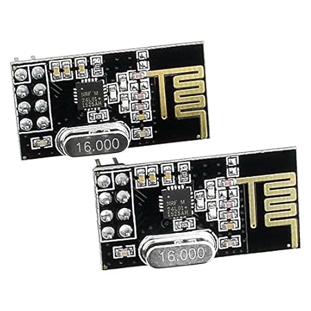
Radios
Ok, I have a base station. How does it communicate with the sensor modules? I needed a low-cost and low-power radio device that I could use to send small data packets. There are lots of interesting products in this space, for example XBee, but they tend to be more expensive than I was hoping for. I did a bit of research and discovered the nRF24L01+ chipset which is used by many very inexpensive radio modules available on Amazon and EBay. There’s good software library support for this module on multiple platforms and it’s very easy to understand and use. The range isn’t great, especially for the modules that use PCB-based antennas, but they’re pretty power-efficient and at a cost of just a dollar or two per radio, it’s hard to beat. (Update: you can also buy versions of the nRF24L01+ radio that have an SMA antenna instead of a PCB antenna, which will significantly increase range.)
Side note: If you want to try using the nRF24L01+ radio on its own or prototype with it for your other projects, check out this breadboard adapter for the nRF24L01+ that I designed to make it easier to experiment with. It separates the rows of pins so you can plug it into a breadboard and also includes an on-board 100uF capacitor and on-board 3.3V regulator so you can use it with a 5V device like the Arduino Uno. The nRF24L01+ requires 3.3V power but is 5V tolerant on its I/O pins so you don’t need a level shifter.
Processor
Now we can turn our attention to the sensor modules themselves, which is the most interesting part of this project from an electronics perspective. I didn’t find anything on the market that did exactly what I wanted to do so I decided to design my own sensors from scratch (which, again, is half the fun).
I’m pretty comfortable with the Arduino ecosystem and I’ve already done several projects using a bare ATMega328P chip which is the processor on an Arduino Uno. The ATMega328P can be programmed to operate in a low-power mode that doesn’t draw much current and it has more than enough compute resources to drive the sensor module, since all it really needs to do is query a hardware temperature sensor device and then send that data to the radio module. Also, it’s available in surface-mount packages that would allow me to minimize the size of the circuit board.

Temperature sensor
There are few commonly-used temperature sensors for hobbyists, including the TMP36 and the DS18B20, but there are other sensors on the market which have better resolution and accuracy ratings and since I was designing this thing from scratch, I figured I might as well go all the way so I chose the MCP9808 which has a typical accuracy of 0.25°C and a maximum resolution of 0.0625°C. It’s not as popular in the hobby space because it’s only available in surface-mount packages, but I wanted to do an SMD board design for this project anyway and there are Arduino driver libraries that make communication easy.
Batteries and voltage regulator
I wanted the sensor modules to be able to run for a year or more on a single set of batteries because I’m lazy and don’t want to be changing batteries all the time. That implied two things: a) I need to use batteries that have low self-discharge rates and b) the sensor board needs to be able to operate from the maximum voltage supplied by fresh batteries all the way down to the minimum voltage supplied by exhausted batteries.
I initially considered using a rechargeable LiPo battery but lithium batteries typically don’t have very good self-discharge rates. That is, a typical LiPo battery will lose about 10% of its charge per month just sitting there while a modern rechargeable AA battery like the Enerloop brand will lose about 0.3% per month. In addition, my sensors don’t have any high-current needs that LiPos are well-suited for, so rechargeable AAs definitely made the most sense.
Looking at the various components I had already picked out, each part had its own voltage operating range but everything seemed to overlap nicely in the 2.7V – 3V range. AA batteries hit about 0.9V when they’re almost all the way drained, so three of them in series would allow me to use practically all of the energy in a set of batteries before shutting down. However, a fresh AA cell can deliver up to 1.6V, or 4.8V for three of them in series, which is more than the absolute maximum voltage of the nRF24L01+ radio (3.6V). So clearly we need a voltage regulator.
Now, we could just drop a basic 3.3V regulator like the LD1117V33 into the circuit but that device has a few major problems for our application. One, it has a voltage drop of ~1.1V, which means that in order to supply 3.3V it has to be fed at least 4.4V, which means the batteries would have to be practically brand new. Two, even if we did have enough source voltage range (maybe by adding more AA cells), the quiescent current of that device is around 5 mA. That means that even if we’re drawing no current at all into the rest of the circuit, the regulator itself will burn 5 mA just sitting there, and there’s no way we’re going to last a year with that kind of power drain.
I did some research and found the MCP1700 which is great regulator for my particular application. It can be ordered in a variety of low-power output voltages, including 3.0V which is what I want. The quiescent current is only 1.8 µA, which is crazy low, and the dropout voltage at the tiny current levels we’re going to operating at is roughly 25mV or less, which is also crazy low. Finally, it’s available in a surface-mount SOT-23 package which is great. This part can only deliver 250 mA of output current but we’re not going to draw anywhere near that anyway, so I don’t care.
Stay tuned
That’s enough words to start with! In the next post I’ll go into detail on how I designed and built the sensor board.

3 thoughts on “Building a wireless temperature sensor network, Part 1”