A Simple Telepresence Robot

I’m teaching a high school astronomy class this year (which I thoroughly enjoy, by the way!), and one of my students lives a couple hours away and uses Skype to attend the class sessions.  The class features a lot of group discussion and it’s kind of difficult for this student to follow what’s going on when all he can see on the screen is me.  I thought, “wouldn’t it be great if the student could rotate the camera around to see who’s talking?”

After contemplating that for a few minutes I realized that I could actually build something to enable that pretty quickly.  Most of my projects end up taking weeks of calendar time to complete (a couple hours here, a couple hours there, wait for an order to get shipped, etc.) but this one actually came together over the course of one weekend with parts I had on hand, just like I’ve always dreamed a project should go.

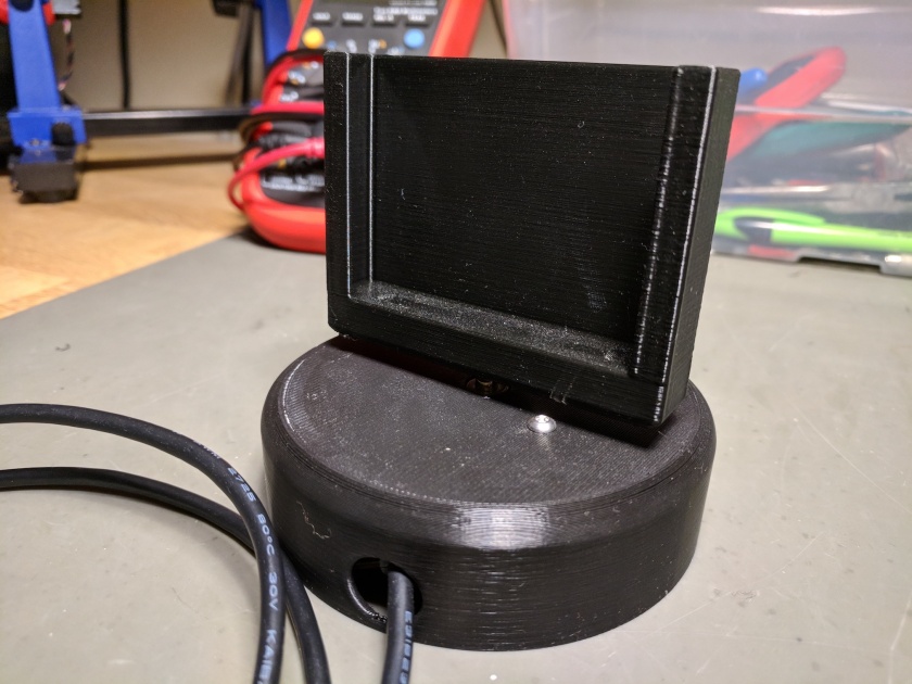
Here’s what the finished project looks like:

IMG_20171119_193623

Design

I usually run the Skype session with the student on my smartphone.  I wanted a device that would have these features:

  • Hold my phone upright in a secure fashion
  • Be able to rotate the phone 360 degrees
  • Allow the student to remotely control the rotation of the device
  • Be reasonably responsive to rotation commands
  • Operate silently so it doesn’t distract the class
  • Be powered from a standard USB port or charger.

I have a 3D printer so building the physical body wasn’t a problem.  I designed a sort of sleeve into which I could insert my phone, which would be attached to the shaft of a motor in the base of the device.

I had an Adafruit stepper motor on hand which was perfect for the job of rotating the phone.  It’s small, practically silent, can rotate 360 degrees, and runs on 5V.  I also had an L293D dual H-bridge motor driver IC suitable for driving this motor.

I’ve used the Particle Photon for a few previous projects and I really like it.  Fortunately I had an extra one on hand which made the remote control part really easy.  Particle has a really fantastic cloud platform that makes it trivial to invoke a function on the device via an HTTP call from anywhere on the internet.  That’s all I needed to build a link between a control web site and the robot.  There’s definitely some risk that Particle may go out of business some day and the cloud services will disappear, but for right now it’s hard to beat the speed with which you can build internet-enabled devices.  I think it’s an acceptable tradeoff for hobby projects like this.

Body

I designed the body of the telepresence robot in Fusion 360.  As an aside, I highly recommend Fusion 360 for designing physical objects where you might need to iterate on the proper physical size, because you can easily go back and change just the dimensions you need to tweak without rebuilding the whole object.  You can get a free hobbyist license as long as you’re not using it for profit.

The CAD files and STL files are available on Thingiverse.  I sized the sleeve for my Google Pixel phone, but if you download the Fusion 360 source file you can easily tweak the dimensions to fit whatever device you’re using.

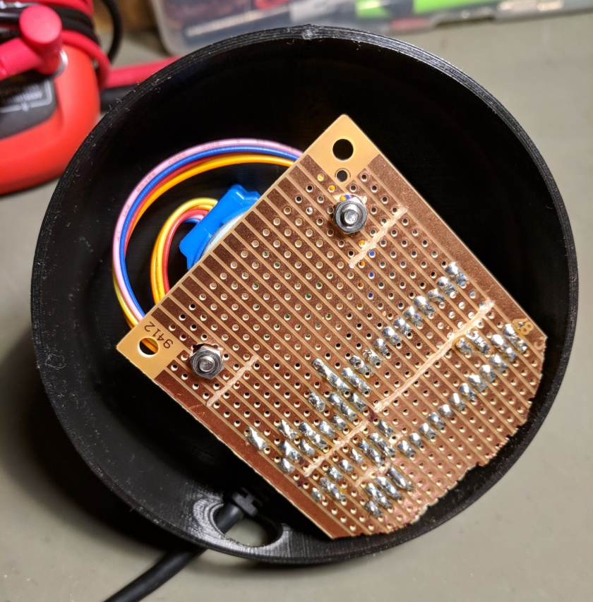
The stepper motor is mounted inside the base using two 25mm M3 buttonhead screws.  It’s important to use screws with very shallow heads so that you get enough clearance for the phone sleeve to rotate above them.  The same two screws also hold the perfboard with the electronics.

The phone sleeve is attached directly to the motor shaft using a small set screw on the back.
IMG_20171119_193418

IMG_20171119_194528

Electronics

I used stripboard to solder the electronics together, but regular perfboard would work just as well.  I based the circuit on this Adafruit tutorial diagram, but using a Photon instead of an Arduino.  Power to the L293D comes from the VIN pin on the Photon which is powered directly from the USB port.  The layout needs to be kind of compact to fit in the base but it wasn’t hard to work out a good strategy after a little thought.
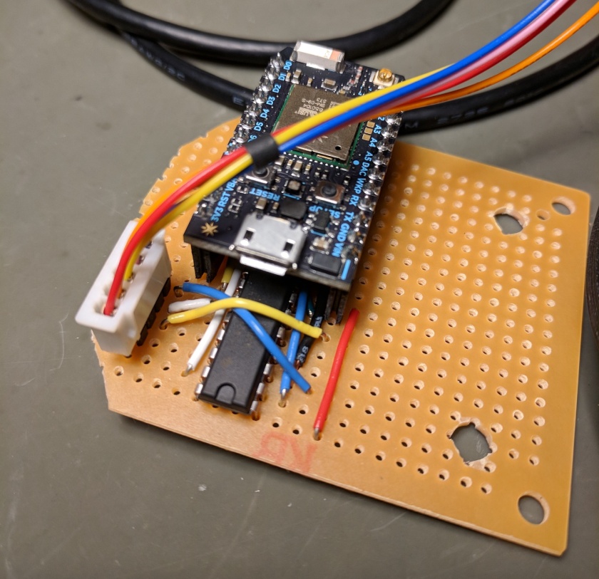
IMG_20171119_194751

Code

The code for the Photon can be found in the GitHub repository, but it’s pretty simple.  Here it is:

#include <Stepper.h>

int in1Pin = D0;
int in2Pin = D1;
int in3Pin = D2;
int in4Pin = D3;

Stepper motor(513, in1Pin, in2Pin, in3Pin, in4Pin);  

void setup() {
  pinMode(in1Pin, OUTPUT);
  pinMode(in2Pin, OUTPUT);
  pinMode(in3Pin, OUTPUT);
  pinMode(in4Pin, OUTPUT);

  motor.setSpeed(8);

   Particle.function("move", moveMotor);
   // This is saying that when we ask the cloud for the function "move", it will employ the function moveMotor() from this app.
}

void loop() {

}

int moveMotor(String command) {
    if (command=="left") {
        motor.step(50);
        return 1;
    }
    else if (command=="right") {
        motor.step(-50);
        return 0;
    }
    else {
        return -1;
    }
}

We’re using the Stepper library that’s available through the Particle cloud-based IDE, which has the same API as the stock Arduino stepper library.  We simply configure four output pins and then implement a function “moveMotor” that can be called remotely through the Particle cloud platform.  When the function is called it receives one string parameter that is the command we should execute, either “left” or “right”, then we just command the motor appropriately.

Web Site

My day job uses the Microsoft stack so the fastest route for me to get to a functional web site was to whip up something using ASP.NET Core.  If you’re more comfortable with Node or whatever, that’s fine too.  The full source code for the remote control web site can be found in the GitHub repository, but here are the important bits minus all the boilerplate code.

The javascript code that runs in the browser just invokes two server APIs:

<script>
    $(function() {
        $('#moveLeft').click(function() {
            $.post("api/moveleft");
        });
        $('#moveRight').click(function() {
            $.post("api/moveright");
        });
    });
</script>

And the code on the server side invokes the function on the Photon:

public class HomeController : Controller
{
    private HttpClient client = new HttpClient();
    private readonly IConfiguration configuration;

    public HomeController(IConfiguration configuration)
    {
        client.BaseAddress = new Uri($"https://api.particle.io/v1/devices/{configuration["device"]}/");
        this.configuration = configuration;
    }

    public IActionResult Index()
    {
        return View();
    }

    public IActionResult Error()
    {
        return View(new ErrorViewModel { RequestId = Activity.Current?.Id ?? HttpContext.TraceIdentifier });
    }

    [Route("api/moveleft")]
    public async Task MoveLeft()
    {
        await DoMove("left");
    }

    [Route("api/moveright")]
    public async Task MoveRight()
    {
        await DoMove("right");
    }

    private async Task DoMove(string direction)
    {
        var content = $"access_token={configuration["access_token"]}&args={direction}";
        await client.PostAsync("move", new StringContent(content, Encoding.UTF8, "application/x-www-form-urlencoded"));
    }
}

The call to the Particle cloud platform is done on the server, not the browser, so we can keep the device ID and access token secret.

Screen Shot 2017-11-19 at 9.33.55 PM

I hosted the web site in Azure but it’s using no special services so it can be hosted pretty much anywhere that can host ASP.NET Core apps.  Total response time, from clicking one of the buttons on the web site to having the device rotate the phone, is typically under one second, which is good enough for my purposes.

That’s all you need to an internet-enabled device up and running.  It doesn’t get much simpler than that!

Add a real-time clock to a Beaglebone Black

I’m using a Beaglebone Black to log some science data around the house.  My internet connection isn’t the most reliable in the world so I first cache the data locally on the BBB and upload it separately; this means I need to capture accurate timestamps for the data.  If the BBB reboots due to a power outage or something, I want the timestamps to be accurate even if the device can’t immediately sync the time from the internet, so I need a battery-backed real-time clock.

As I researched the proper way to do this, I discovered that there are a lot of articles and forum posts that discuss the topic but most of them had one or both of these problems:

  • They explained how to enable the RTC for the current session but not in a way that would survive reboots.
  • They gave instructions based on old or different OSes that weren’t valid for my device.

I finally put together something that I’m happy with so I’m documenting what I found.  None of this information is original discovery on my part but hopefully it’ll be in a form that’s useful to others.  However, it’s important to note that these instructions are for the Beaglebone Black running Debian 9 (Stretch), specifically “Linux beaglebone 4.4.91-ti-r133 #1 SMP Tue Oct 10 05:18:08 UTC 2017 armv7l GNU/Linux”.  They might be helpful for other devices or other Linux flavors but some things are likely to be different.

Hardware

I’m using a really cheap I2C-based DS1307 RTC that I ordered from China, called the Tiny RTC.  This device is available from a bunch of different sources but the design is exactly the same.  It’s actually a poorly-designed device but it’s dirt cheap and can be fixed with a bit of surgery.

Problems

The first problem is that the Tiny RTC is designed to trickle-charge a rechargeable LIR2032 battery, but a) the charging circuit isn’t very good and b) LIR2032 batteries aren’t widely available and tend to be of poor quality.  A regular CR2032 battery will last for years anyway, so it’s better to just disable the charging circuit.  Don’t put a non-rechargeable CR2032 into the device without first disabling the charging circuit; the battery may eventually explode if you do.

The second problem is that the Tiny RTC is designed as a 5V device but the BBB is a 3.3V device.  Fortunately the I2C bus lets us interoperate with 3.3V safely as long as we remove the pull-up resistors from the RTC.

The third problem is that the crystal oscillator is supposed to be soldered to the ground pad underneath it, according to the internet, but usually it’s not.  This can cause stability problems.

Another potential problem is that DS1307 chip doesn’t keep very good time and is sensitive to temperature variations, but since I planned to have the BBB regularly update the time on the RTC, that didn’t matter much to me.

Fixing the hardware

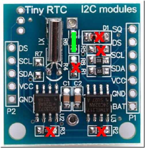
Here’s a picture of the board:

image

  • To disable the charging circuit, remove D1, R4, R5, R6, and short the R6 pads together.
  • To make the device compatible with the 3.3V BBB, remove R2 and R3.  If you plan to use the square wave output, remove R8 too.
  • Carefully solder the body of the crystal to the ground pad underneath it.  Do this rapidly so you don’t overheat the crystal.

Connecting to the Beaglebone

Refer to one of the many Beaglebone Black pinout diagrams available on the web.

  • Connect VCC to P9-05
  • Connect GND to P9-01
  • Connect SCL to P9-19
  • Connect SDA to P9-20

Note that the I2C pins on the BBB are for I2C-2.  This may be different on other devices, which would change many things below.

Test the hardware

You can test your work so far by running this command on the BBB:

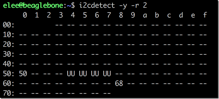
i2cdetect -y -r 2

If the RTC is wired correctly and is communicating properly, you’ll see this output indicating that there’s a device at address 0x68:

image

Software

As I mentioned earlier, the challenge with setting up the RTC is to do it in a way that survives reboots and doesn’t require further manual intervention.  Most of the following instructions came from Mike Kazantsev’s excellent blog post with a few details filled in or tweaked for my specific environment.  He wrote some great technical explanations which I won’t attempt to duplicate here; if you want to know why the following steps work, read his post.

Add the RTC to the device tree

To make the kernel aware of the RTC device and to have it enabled at boot, we need to add it to the device tree.  Create a file named i2c2-rtc-ds1307.dts in your home folder with this content:

/dts-v1/;
/plugin/;

/* dtc -O dtb -o /lib/firmware/BB-RTC-02-00A0.dtbo -b0 i2c2-rtc-ds3231.dts */
/* bone_capemgr.enable_partno=BB-RTC-02 */
/* https://github.com/beagleboard/bb.org-overlays */

/ {
  compatible = "ti,beaglebone", "ti,beaglebone-black", "ti,beaglebone-green";
  part-number = "BB-RTC-02";
  version = "00A0";

  fragment@0 {
    target = ;

    __overlay__ {
      pinctrl-names = "default";
      pinctrl-0 = ;
      status = "okay";
      clock-frequency = ;
      #address-cells = ;
      #size-cells = ;

      rtc: rtc@68 {
        compatible = "dallas,ds1307";
        reg = ;
      };
    };
  };
};

Next, run this command to compile the overlay file and place the resulting overlay in your firmware directory:

sudo dtc -O dtb -o /lib/firmware/BB-RTC-02-00A0.dtbo -b0 i2c2-rtc-ds3231.dts

You may see a warning during compilation but it appears to be benign.

Now we need to tell the kernel to load that device overlay on boot.  Edit /boot/uEnv.txt and find the line that says, “###Custom Cape”.  Directly below that line, enable the example overlay line and make it look like this:

###Custom Cape
dtb_overlay=/lib/firmware/BB-RTC-02-00A0.dtbo

Now reboot and run this command:

ls -al /dev/rtc*

You should see this output:

image

Notice that we now have RTC0 and RTC1 devices.  RTC0 is the built-in hardware clock in the BBB but it has no battery backup.  RTC1 is the DS1307 that we connected to the BBB, so now we have two hardware clocks available.  We’re not done, though, because the /dev/rtc symlink is pointing to RTC0, not RTC1.

Make our RTC the default

We can add a udev rule that will symlink to our battery-backed RTC instead.  Create a new file named /etc/udev/rules.d/55-i2c-rtc.rules with this text:

SUBSYSTEM=="rtc", KERNEL=="rtc1", SYMLINK+="rtc", OPTIONS+="link_priority=10", TAG+="systemd"

Now reboot and run this command:

ls -al /dev/rtc*

You should see this output:

image

Now the /dev/rtc symlink points to our DS1307 RTC.

Set system time from RTC

Now we have our new RTC set up but the system time still won’t be set on boot.  The systemd-timesyncd service is responsible for time syncing in this build of Debian.  As it syncs the time from a time server it writes that time to disk.  If the device reboots and has no internet connection, systemd-timesyncd will see that the system time is unset and will load the last-synced time from disk and use that to set the system time (which wouldn’t be correct, but at least closer than a totally unset time).  We need to set the system time from our RTC before systemd-timesyncd checks it, and we can do that by creating a new systemd service.

Create a file named /etc/systemd/system/i2c-rtc.service with this text:

[Unit]
ConditionCapability=CAP_SYS_TIME
ConditionVirtualization=!container
DefaultDependencies=no
Wants=dev-rtc.device
After=dev-rtc.device
Before=systemd-timesyncd.service ntpd.service chrony.service

[Service]
Type=oneshot
CapabilityBoundingSet=CAP_SYS_TIME
PrivateTmp=yes
ProtectSystem=full
ProtectHome=yes
DeviceAllow=/dev/rtc rw
DevicePolicy=closed
ExecStart=/sbin/hwclock -f /dev/rtc --hctosys

[Install]
WantedBy=time-sync.target

Then run this command to enable the service to start on boot:

sudo systemctl enable i2c-rtc

Set the RTC from system time

As mentioned above, systemd-timesyncd will regularly correct the system time from a time server whenever you have an internet connection.  I thought that systemd-timesyncd would also update the default hardware clock at the same time, but it doesn’t.  Turns out it’s the kernel’s job to regularly copy the system time to the hardware clock, but the kernel actually targets /dev/rtc0 directly rather than using the /dev/rtc symlink, and this is set as a compilation option, not a runtime option, so it can’t be easily changed.  Instead of recompiling the kernel we’re just going to add another systemd service which will regularly update our RTC with the correct time.  This is particularly important since the DS1307 isn’t a very good clock and will drift significantly in only a few days.

First create a service file named /etc/systemd/system/systohc.service with this text:

[Unit]
ConditionCapability=CAP_SYS_TIME
ConditionVirtualization=!container
DefaultDependencies=no
Wants=dev-rtc.device
After=systemd-timesyncd.service

[Service]
Type=oneshot
CapabilityBoundingSet=CAP_SYS_TIME
PrivateTmp=yes
ProtectSystem=full
ProtectHome=yes
DeviceAllow=/dev/rtc rw
DevicePolicy=closed
ExecStart=/sbin/hwclock -f /dev/rtc --systohc

We want this service to run periodically to keep the hardware clock updated, so create a file named /etc/systemd/system/systohc.timer with this text:

[Unit]

[Timer]
OnUnitActiveSec=1h
OnBootSec=10s

[Install]
WantedBy=timers.target

Now enable the timer to start on boot with this command:

sudo systemctl enable systohc.timer

At this point we’re done with the software configuration, but don’t reboot yet because we want to do some testing.

Testing

To test that everything is working as expected, first set the DS1307 clock to some obviously incorrect date using this command:

sudo hwclock -f /dev/rtc1 –set –date=”2017-01-01 00:00:01″ –utc

Next, physically unplug any internet connection (wifi/ethernet) from the BBB and reboot.  When the BBB comes back up without an internet connection, running date at the command line should show you the incorrect date you set above.  This tells us that the date was loaded from the DS1307 on boot, which is what we want.

Now reconnect your internet connection, wait a minute or two, then check the system clock and both hardware clocks with this command:

date && sudo /sbin/hwclock -r -f /dev/rtc0 && sudo /sbin/hwclock -r -f /dev/rtc1

This will print out three date/time strings and they should all be the same (to within a few seconds since the commands to print each one are running sequentially).  This tells us that the system clock was synced from the time server and the updated time was also copied to both hardware clocks, which is what we want.

If you walk through these instructions and find errors or clarifications, leave a comment below.