This is part 4 of a series of blog posts documenting how I designed and built a multi-node wireless temperature sensor system. Links to all of the posts in the series:
- Part 1: Requirements and general design
- Part 2: Sensor module hardware
- Part 3: Sensor modules software
- Part 4: The base station
All hardware and software files for the project can be found in my GitHub repository.
The Base Station
Someone recently contacted me about this project and asked for more details about the base station that collects data from the remote sensors. I didn’t bother to create a proper PCB for that part of the project, instead just soldering something together with perfboard, but I’m happy to share pictures and details about what I did.
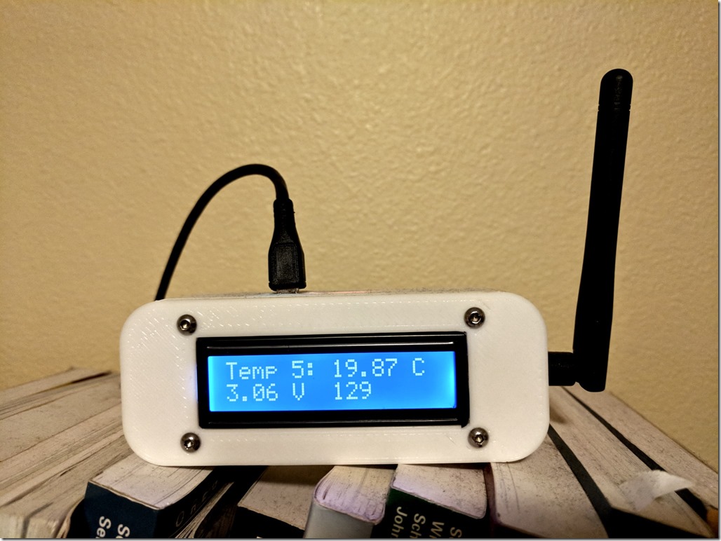
The base station sits on top of a bookshelf, out of the way. It’s powered from a USB adapter and all of my sensors are close enough that reception isn’t a problem. I chose to use a nRF24L01+ radio that has an SMA antenna for greater range. (It’s also a good idea to use that same radio on any remote sensors that are having trouble maintaining communication – it makes a big difference.) The display isn’t critical because I push the data to a web site where I can view pretty graphs and such, but it’s useful for troubleshooting. It continuously cycles through the temperature and supply voltage for each of the five remote sensors. The number in the lower right is the number of times the base station displayed stale data for a sensor (because it failed to receive a recent reading). That gives gives me a rough idea of whether I’ve got reception problems. The count of 129 is pretty low considering that’s been accumulating since the last time our household power blinked (several weeks).
The display module is a standard 16×2 character LCD display I bought from Ebay plus an I2C LCD backpack I bought from Banggood. You could get something equivalent (though more expensive) from Sparkfun or Adafruit. I covered the end of the LCD and an LED on the backpack with black tape to reduce distracting light bleed.
I designed the case in Fusion 360 and printed it on my 3D printer. It’s somewhat specific to the prototyping board I used, but you can get the design files from my GitHub repository.
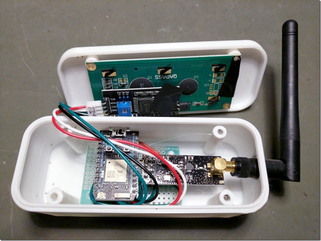
Here’s what the inside looks like:
The Circuit Board
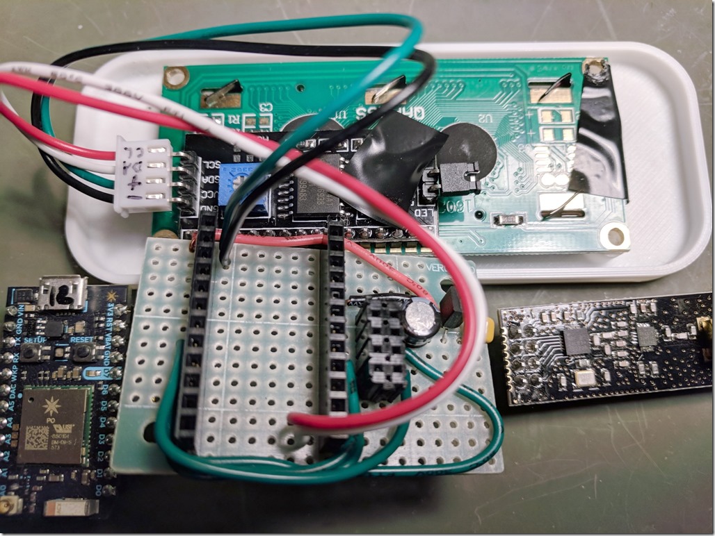
I don’t have a schematic or a PCB layout for the circuit board but it’s pretty simple so a description should suffice. The Particle Photon is powered from a micro-USB cable and we use the raw 5V pin on the Photon to power the display and the radio. The display is 5V-native, so that’s fine. The radio is actually 3.3V, and at first you might think you could power it from the Photon’s 3.3V pin (using the Photon’s onboard regulator), but after looking at the numbers I decided that the Photon’s 3.3V regulator wasn’t going to be able to power both the Photon itself and the radio (which can have high current spikes), so I actually ran the 5V line over to a separate 3.3V regulator (MCP1700-3302E/TO) and associated capacitors on the board and powered the radio that way.
The code that runs on the Photon can be found in the GitHub repository. The correct connections between the Photon and the radio can be found in comments at the top of the code file (MOSI, MISO, and SCK).
When I first started running this system I was forwarding events from the Particle cloud to my private Phant server, but SparkFun has since deprecated Phant so I switched to using a hosted virtual machine with ElasticSearch, Logstash, and Kibana (commonly known as the ELK stack). You could also use Adafruit.io, ThingSpeak, Blynk, or whatever platform you prefer.


3 thoughts on “Building a wireless temperature sensor network, Part 4”