This is part 3 of a series of blog posts documenting how I designed and built a multi-node wireless temperature sensor system. Links to all of the posts in the series:
- Part 1: Requirements and general design
- Part 2: Sensor module hardware
- Part 3: Sensor modules software
- Part 4: The base station
All hardware and software files for the project can be found in my GitHub repository.
Programming the sensor module
Once you finish soldering a sensor module, the next thing you have to do is to set some configuration options and upload the firmware. To do this, you’ll need an AVR programmer device of some kind. We can’t use a simple USB cable like you can with an Arduino because a) we didn’t include USB components on the board and b) the processor doesn’t have any bootloader firmware installed.
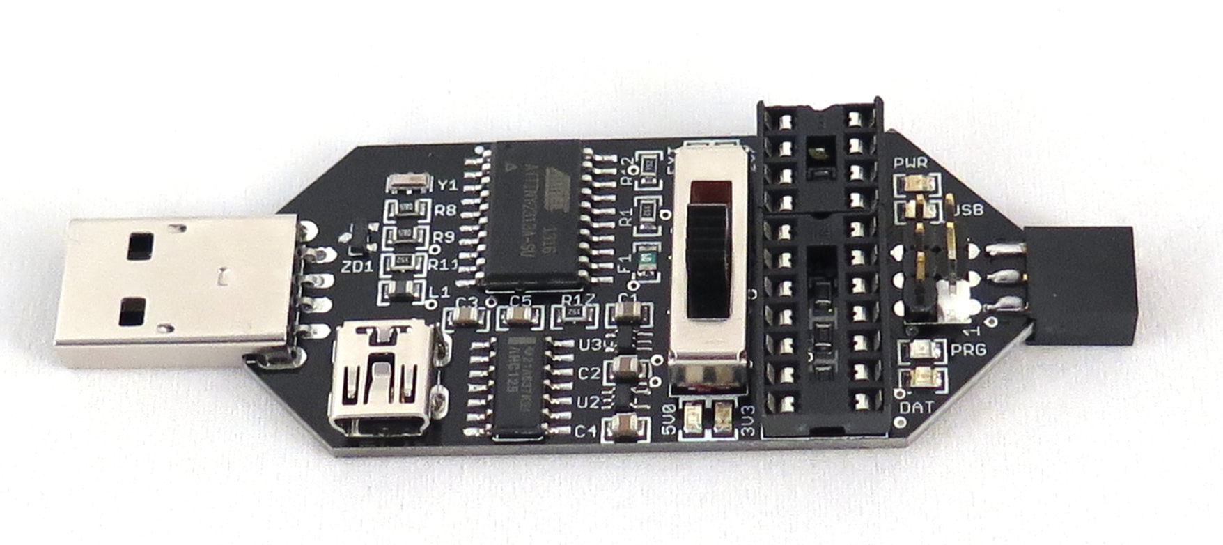
There are a couple of different possible approaches for programming AVR processors. If you don’t have a purpose-built programmer device but you do have an Arduino on hand, you can use the Arduino as your programmer. There are also a variety of USB-based programmer devices you can buy; you can buy an inexpensive kit from Adafruit or I really like this one that’s sold by Femtocow on Tindie:
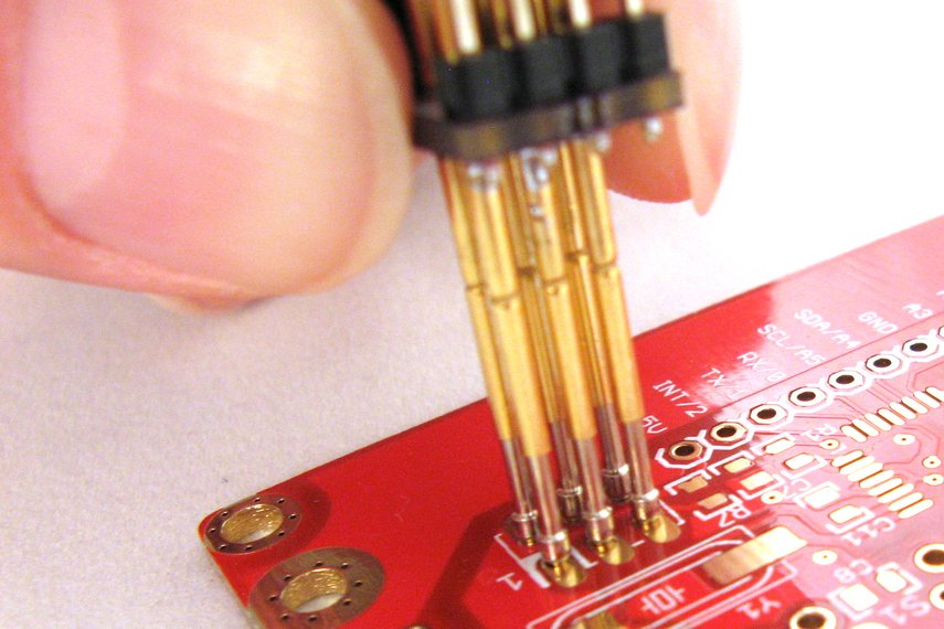
Once you have a programmer you need to connect it to the ICSP header on the sensor module. You can either solder on headers and use a cable option of your choice or you can get this nice pogo-pin adapter, also from Femtocow:
Setting the fuses
Once you have your programming system set up, the first thing we need to do is set the “fuses” which are hardware level configuration options that control certain behaviors of the microprocessor. In particular, we want to set the processor frequency to 8Mhz, tell the processor to preserve its EEPROM memory when it’s programmed, and set the brown-out detection feature to trigger at 2.7V. If you’re using one of the USBtinyISP programmers I linked above you can use this command line to set the fuses:
avrdude -c usbtiny -p m328p -U lfuse:w:0xe2:m -U hfuse:w:0xd1:m -U efuse:w:0xfd:m
If you use a different kind of programmer you’ll probably have to use a different value for the –c parameter to tell avrdude which programmer you’re using.
The board core
Because we’re going to run the ATMEGA328P at 8 MHz, we need to use an Arduino board core that supports that clock speed. The OSHLab Breadboard Arduino core works well for this; follow the installation instructions for adding it to your board manager, then install the core, then select the “ATmega328p (8mhz internal)” board from the list of boards.
Setting the ID
For reasons that will be clear a little later, the next thing we have to do is to give the sensor module a unique ID. To do that, I use the id sketch in my GitHub repository. (I’m not going to copy the source code here so that it won’t get out of date.) Open the id.ino sketch in the Arduino IDE and set the nodeId variable to an integer between 1 and 9. This value will become the ID of the sensor module (stored in EEPROM so it survives reboots) after it runs this sketch. Once you’ve set an ID, upload the code to the sensor and you should see the onboard LED repeatedly blink a pattern that indicates the ID you set. If you don’t see the LED blinking at all then either the programming didn’t complete successfully or you forgot to change the nodeId variable from its default value of 0.
The sensor module firmware
Finally we can upload the sensor module firmware sketch from GitHub. Note that there are also two supporting files MCP9808.h and MCP9808.cpp in the same folder that you have to have in order to compile the sketch. You can upload this sketch to the sensor module, overwriting the ID sketch, because the ID you programmed is saved in EEPROM memory.
Let’s look at some of the highlights of this code. I’ll include relevant snippets here but remember that the version on GitHub is always the most up-to-date.
Setup
void setup(void)
{
  initializePins();
  loadNodeAddress();
  initializePeripherals();
}
When the processor first starts we do a few one-time things:
- Configure the GPIO pins (that aren’t otherwise configured by libraries) for our use. Right now there’s only the LED output pin.
- Load the node address from EEPROM. That function verifies that the ID it loaded is between 1 and 9 and if it’s not, it’ll blink the LED rapidly and continuously to indicate an error condition.
- Initialize the radio and temperature sensor. The radio is configured to transmit at maximum power and the slowest bitrate in order to get decent range. We don’t transmit very often or for long so this doesn’t hurt our battery life too badly.
Loop
Once everything is initialized we can start running the code that collects data and transmits it to the base station. The high-level loop looks like this:
void loop(void)
{
  wakePeripherals();
  sendData();
  shutDownPeripherals();
  longSleep();
}
We wake up the peripherals from their sleep states, then we send the our collected data to the base station, then we put the peripherals back to sleep, then we put the processor itself to sleep. Eight seconds later a timer wakes up the processor and we do the whole thing again, and this repeats forever.
Waking
Waking up the peripherals is interesting because the temperature sensor has some special considerations. This is how we do it:
void wakePeripherals()
{
  // When we wake the sensor it takes time to do another conversion.
  // The time depends on the configured resolution (250ms for highest res.). We need to wait
  // until the sensor has had time to do another conversion after
  // waking or we'll just end up reading the previous conversion.
  sensor.wake();
  shortSleep();
  radio.powerUp();
}
When the MCP9808 temperature sensor first wakes up, it starts doing another reading but if you immediately ask it for a reading before it’s finished it’ll just give you the result of the last reading it took. We need wait long enough to allow the sensor to finish taking its new reading, then we can ask it for the new data. The code wakes up the sensor then puts the processor back to sleep for 288 milliseconds. Once that time elapses then we can wake up the radio because we’re about to send out new data.
Sending data
Sending the data is pretty straightforward:
void sendData()
{
  int16_t buffer[2];
  buffer[0] = sensor.readTempC() * 16;
  buffer[1] = getBandgap();
  bool success = radio.write(buffer, sizeof(buffer));
  if (!success)
  {
    blinkIndicatorLed();
  }
}
We’re sending two 16-bit integers to the base station. The first is the temperature in Celsius, encoded to an integer by multiplying it by 16 (the sensor measures temperature in 1/16 degree increments). The second integer is the voltage that the processor is receiving from the voltage regulator.
I considered adding circuitry to allow the processor to sample the unregulated battery supply voltage, which would be a more interesting number, but at the time I was worried about input pin leakage current, so I decided to do something a little less cool and just have the processor measure its own supply voltage. That will be really close to 3.0V constantly until the battery pack is close to exhausted and the regulator is forced out of regulation and the voltage starts to drop below 3V. When that happens I know it’s time to change the battery. In hindsight I think leakage current would be trivial and I should have at least included the ability to sample the raw voltage, so I’ll probably add that if I spin a new rev of the sensor module board.
By the way, I didn’t write the code that measures the processor’s power supply voltage; I got it from Nick Gammon’s blog (which is amazing and highly recommended).
If we’re successful in sending the data then nothing further happens. We don’t want to blink an LED in this case because that’s just wasted power. But if the transmit doesn’t succeed for some reason then we do blink the LED to indicate that something went wrong. If the sensor is transmitting and being received correctly then this will hardly ever happen and if it’s not working correctly then battery life doesn’t really matter.
Sleeping
There’s some very specific code that needs to run in order to put the processor into its lowest-power sleep state, and once again I didn’t write it myself but instead got it from Nick Gammon’s blog, so go there to understand the mechanics of how it works.


please i need to talk to some one on this i need to know ho to built a simple temperature sensor node please