Building a wireless temperature sensor network, Part 3

This is part 3 of a series of blog posts documenting how I designed and built a multi-node wireless temperature sensor system.  Links to all of the posts in the series:

All hardware and software files for the project can be found in my GitHub repository.

Programming the sensor module

Once you finish soldering a sensor module, the next thing you have to do is to set some configuration options and upload the firmware.  To do this, you’ll need an AVR programmer device of some kind.  We can’t use a simple USB cable like you can with an Arduino because a) we didn’t include USB components on the board and b) the processor doesn’t have any bootloader firmware installed.

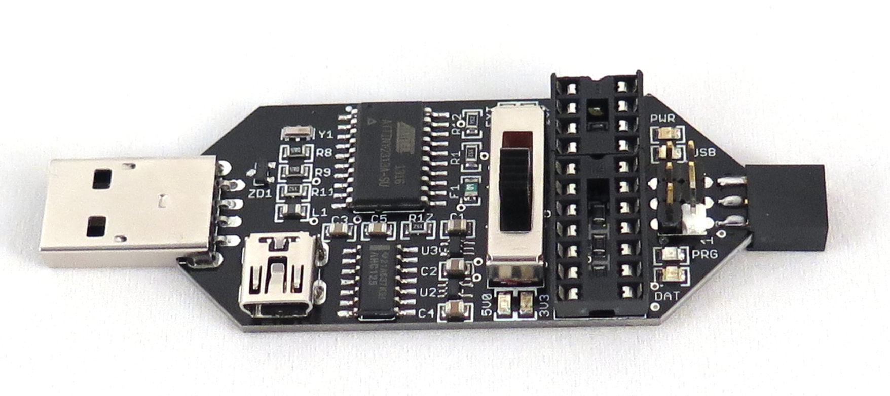
There are a couple of different possible approaches for programming AVR processors.  If you don’t have a purpose-built programmer device but you do have an Arduino on hand, you can use the Arduino as your programmer.  There are also a variety of USB-based programmer devices you can buy; you can buy an inexpensive kit from Adafruit or I really like this one that’s sold by Femtocow on Tindie:

image

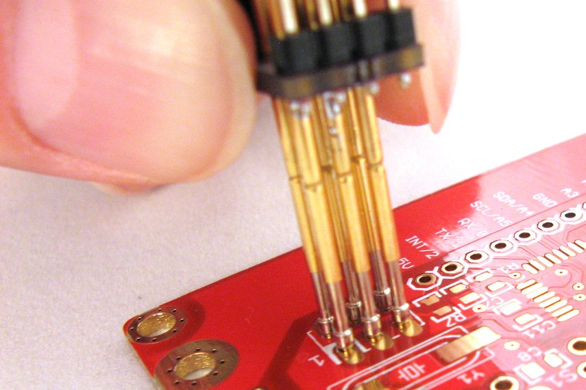
Once you have a programmer you need to connect it to the ICSP header on the sensor module.  You can either solder on headers and use a cable option of your choice or you can get this nice pogo-pin adapter, also from Femtocow:

image

Setting the fuses

Once you have your programming system set up, the first thing we need to do is set the “fuses” which are hardware level configuration options that control certain behaviors of the microprocessor.  In particular, we want to set the processor frequency to 8Mhz, tell the processor to preserve its EEPROM memory when it’s programmed, and set the brown-out detection feature to trigger at 2.7V.  If you’re using one of the USBtinyISP programmers I linked above you can use this command line to set the fuses:

avrdude -c usbtiny -p m328p -U lfuse:w:0xe2:m -U hfuse:w:0xd1:m -U efuse:w:0xfd:m

If you use a different kind of programmer you’ll probably have to use a different value for the –c parameter to tell avrdude which programmer you’re using.

The board core

Because we’re going to run the ATMEGA328P at 8 MHz, we need to use an Arduino board core that supports that clock speed.  The OSHLab Breadboard Arduino core works well for this; follow the installation instructions for adding it to your board manager, then install the core, then select the “ATmega328p (8mhz internal)” board from the list of boards.

Setting the ID

For reasons that will be clear a little later, the next thing we have to do is to give the sensor module a unique ID.  To do that, I use the id sketch in my GitHub repository.  (I’m not going to copy the source code here so that it won’t get out of date.)  Open the id.ino sketch in the Arduino IDE and set the nodeId variable to an integer between 1 and 9.  This value will become the ID of the sensor module (stored in EEPROM so it survives reboots) after it runs this sketch.  Once you’ve set an ID, upload the code to the sensor and you should see the onboard LED repeatedly blink a pattern that indicates the ID you set.  If you don’t see the LED blinking at all then either the programming didn’t complete successfully or you forgot to change the nodeId variable from its default value of 0.

The sensor module firmware

Finally we can upload the sensor module firmware sketch from GitHub.  Note that there are also two supporting files MCP9808.h and MCP9808.cpp in the same folder that you have to have in order to compile the sketch.  You can upload this sketch to the sensor module, overwriting the ID sketch, because the ID you programmed is saved in EEPROM memory.

Let’s look at some of the highlights of this code.  I’ll include relevant snippets here but remember that the version on GitHub is always the most up-to-date.

Setup

void setup(void)
{
  initializePins();
  loadNodeAddress();
  initializePeripherals();
}

When the processor first starts we do a few one-time things:

  1. Configure the GPIO pins (that aren’t otherwise configured by libraries) for our use.  Right now there’s only the LED output pin.
  2. Load the node address from EEPROM.  That function verifies that the ID it loaded is between 1 and 9 and if it’s not, it’ll blink the LED rapidly and continuously to indicate an error condition.
  3. Initialize the radio and temperature sensor.  The radio is configured to transmit at maximum power and the slowest bitrate in order to get decent range.  We don’t transmit very often or for long so this doesn’t hurt our battery life too badly.

Loop

Once everything is initialized we can start running the code that collects data and transmits it to the base station.  The high-level loop looks like this:

void loop(void)
{
  wakePeripherals();
  sendData();
  shutDownPeripherals();
  longSleep();
}

We wake up the peripherals from their sleep states, then we send the our collected data to the base station, then we put the peripherals back to sleep, then we put the processor itself to sleep.  Eight seconds later a timer wakes up the processor and we do the whole thing again, and this repeats forever.

Waking

Waking up the peripherals is interesting because the temperature sensor has some special considerations.  This is how we do it:

void wakePeripherals()
{
  // When we wake the sensor it takes time to do another conversion.
  // The time depends on the configured resolution (250ms for highest res.). We need to wait
  // until the sensor has had time to do another conversion after
  // waking or we'll just end up reading the previous conversion.
  sensor.wake();
  shortSleep();
  radio.powerUp();
}

When the MCP9808 temperature sensor first wakes up, it starts doing another reading but if you immediately ask it for a reading before it’s finished it’ll just give you the result of the last reading it took.  We need wait long enough to allow the sensor to finish taking its new reading, then we can ask it for the new data.  The code wakes up the sensor then puts the processor back to sleep for 288 milliseconds.  Once that time elapses then we can wake up the radio because we’re about to send out new data.

Sending data

Sending the data is pretty straightforward:

void sendData()
{
  int16_t buffer[2];
  buffer[0] = sensor.readTempC() * 16;
  buffer[1] = getBandgap();
  bool success = radio.write(buffer, sizeof(buffer));
  if (!success)
  {
    blinkIndicatorLed();
  }
}

We’re sending two 16-bit integers to the base station.  The first is the temperature in Celsius, encoded to an integer by multiplying it by 16 (the sensor measures temperature in 1/16 degree increments).  The second integer is the voltage that the processor is receiving from the voltage regulator.

I considered adding circuitry to allow the processor to sample the unregulated battery supply voltage, which would be a more interesting number, but at the time I was worried about input pin leakage current, so I decided to do something a little less cool and just have the processor measure its own supply voltage.  That will be really close to 3.0V constantly until the battery pack is close to exhausted and the regulator is forced out of regulation and the voltage starts to drop below 3V.  When that happens I know it’s time to change the battery.  In hindsight I think leakage current would be trivial and I should have at least included the ability to sample the raw voltage, so I’ll probably add that if I spin a new rev of the sensor module board.

By the way, I didn’t write the code that measures the processor’s power supply voltage; I got it from Nick Gammon’s blog (which is amazing and highly recommended).

If we’re successful in sending the data then nothing further happens.  We don’t want to blink an LED in this case because that’s just wasted power.  But if the transmit doesn’t succeed for some reason then we do blink the LED to indicate that something went wrong.  If the sensor is transmitting and being received correctly then this will hardly ever happen and if it’s not working correctly then battery life doesn’t really matter.

Sleeping

There’s some very specific code that needs to run in order to put the processor into its lowest-power sleep state, and once again I didn’t write it myself but instead got it from Nick Gammon’s blog, so go there to understand the mechanics of how it works.

Building a wireless temperature sensor network, Part 2

This is part 2 of a series of blog posts documenting how I designed and built a multi-node wireless temperature sensor system.  Links to all of the posts in the series:

All hardware and software files for the project can be found in my GitHub repository.

The schematic

In the previous post I talked about how and why I selected some of the major components that went into the sensors.  Now let’s cover the schematic and board design in more detail.  Important disclaimer: I’m not an expert at electrical engineering, I’m just a self-taught hobbyist.  I’m sure I made mistakes along the way.  If you see something in my design that’s wrong, feel free to leave a comment with constructive criticism!

Here’s the schematic for the sensor board (click for larger version):

image

Let’s walk through it piece by piece.

In the top left we have the power subsystem with the MCP1700 regulator that I picked out.  The MCP1700 needs 1µF capacitors on the input and output for stability, and general advice from people who have used the nRF24l01+ radio is that it benefits from a 100µF capacitor nearby to help satisfy current spikes as the radio turns on and off.  I was a little worried about leakage current through the electrolytic capacitor but in practice it appears to be insignificant.

In the top right we have the AVR ICSP header that we’ll use to program the ATMega328P.  In the lower left we have the pin headers for the nRF24L01+ radio to plug into.

The ATMega328P processer is in the bottom middle, obviously, and we have a decoupling capacitor on the power inputs and a pull-up resistor for the reset line.  I debated whether or not to include the reset line pull-up, because it’s not strictly necessary (the reset line has a weak internal pull-up built in), but decided to go ahead and do it in order to avoid potential problems.  I named and labeled the nets for the various data lines and didn’t run actual wires everywhere, which simplifies the diagram.  I went ahead and connected the IRQ line to the radio and the ALERT line to the MCP9808 even though I have no specific plans to use them right now, but they’ll be there if I change my mind.

Finally, in the lower right you will find the MCP9808 temperature sensor and its decoupling capacitor, plus an indicator LED which is very useful for diagnostics and displaying various bits of information about how the sensor module is operating.  I’ve made it a strong rule of thumb to always include at least one diagnostic LED on every board I make, whether I think I need one or not.  It always ends up saving my hide at some point.

The MCP9808 uses I2C for communication and I2C requires pull-up resistors in order to work correctly.  However, I really didn’t want to include external pull-up resistors on this board because a) that means more parts to place and b) the smaller the pull-up resistors are, the more current flows during I2C communication and we want to drive our current needs as low as possible.  I ended up just relying on the internal 20KΩ pull-ups in the ATMega328P and hoped that would be sufficient given the expected low capacitance of the data lines.  (Spoiler alert: it was, just barely.  More on that later.)

The board

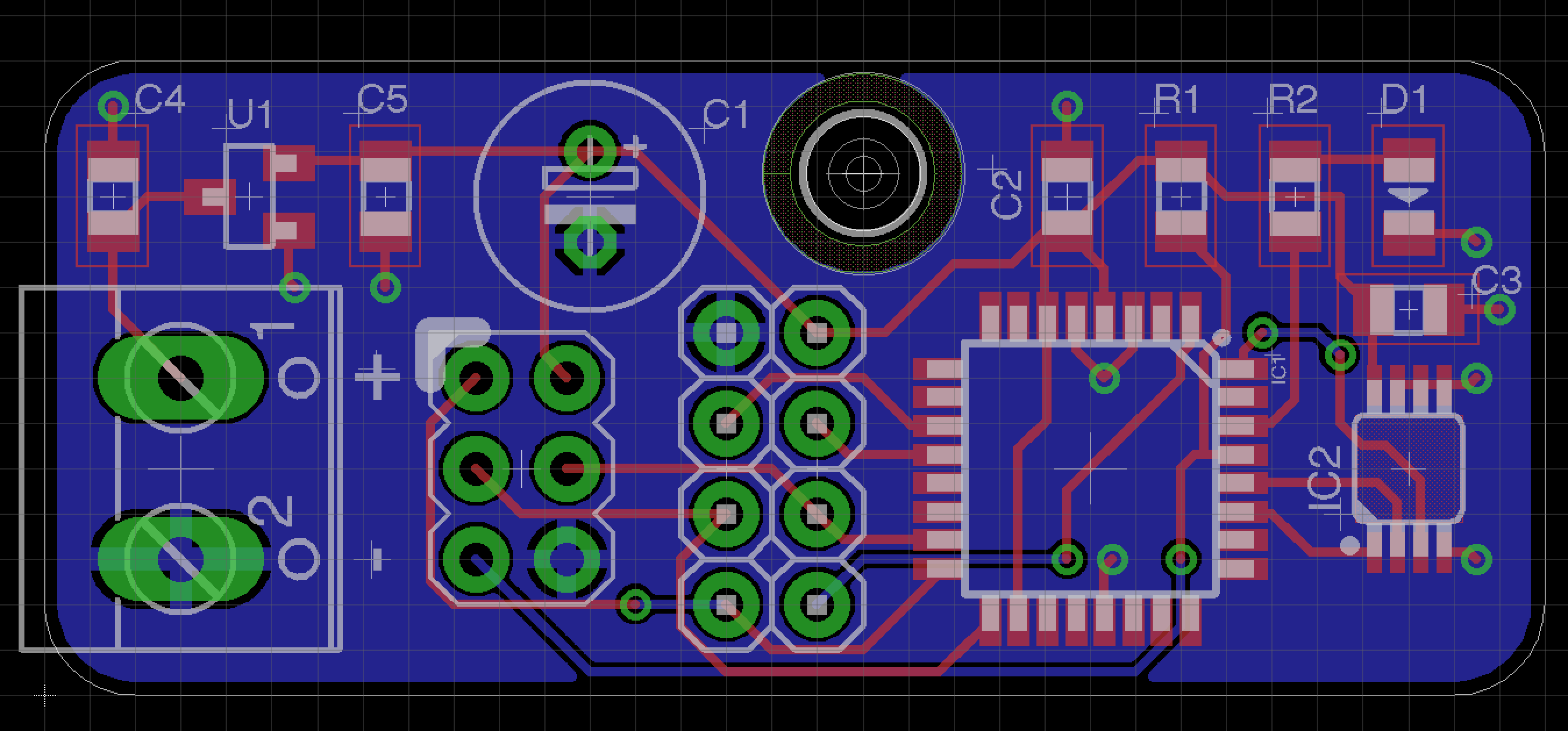
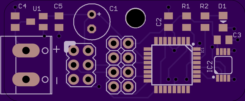
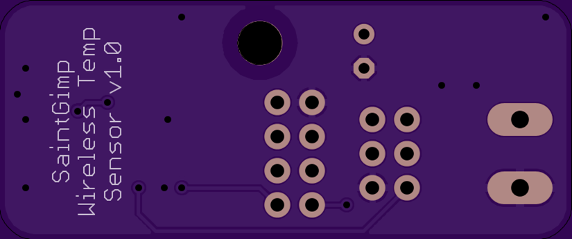
Here’s the board layout (click for a larger version):

image

This is a two-layer board with a ground plane on the bottom and traces on the top.  I tried to minimize the number of traces on the bottom because they can break up the flow of return ground currents if poorly placed but I did have to use a few.  Making a good board layout is definitely an art form, and it probably helps if you’ve played a lot of Tetris.  For me, anyway, it’s largely a process of trial and error.  I start by grouping things that are connected to each other close together on the board, then I nudge things around and rotate parts trying to get the minimum number of crossed wires.  There are certain tricks you learn, like a resistor or capacitor gives you a free bridge to get from one side of a wire to the other, but mostly it’s a giant game of “what if?”

The power connector pads are sized for a standard terminal block but I pretty much ended up soldering the battery pack wires directly to the pads in order to save time and vertical space.

The ICSP header block can be populated with pins or left empty; I have a nice little pogo pin ICSP adapter that allows me to just touch the adapter to the ICSP pads on the board and quickly program the board.  (More about programming in a later post.)  The 100µF capacitor is a small 10V model that isn’t very tall.  The radio gets soldered directly into the 2×4 header in the middle of the board such that the body of the radio module is to the right of the header.  (As I was writing this I noticed that I didn’t do anything to mark that in the silkscreen, which is a mistake I should fix.)

The physical dimensions are roughly 42mm by 18mm, which is nice and small.  There’s one mounting hole and I rounded the corners of the board a bit to make it look nice.

I had the boards manufactured by OshPark (project shared here) and it cost me $5.75 for three of them, which is mind-blowing.  This really is a golden age for hobby electronics.  Everything worked on the first try, which I was pleased with.

image

image

Assembly

This was one of my first SMT projects and I learned a lot about SMT soldering techniques.  My purpose here is not to write a general SMT soldering tutorial because there are lots of excellent ones already available and I can’t improve on them, but here are some general tips that were particularly useful for me:

  1. Watch a lot of how-to videos on YouTube.  Don’t stop with just one; each video adds something unique and gives you a better overall picture of how it works.
  2. Liquid flux is an absolute must-have.  If you try to skip it, you’re going to have a bad time.  Trust me on this.
  3. Use a small pointy tip on your soldering iron for soldering small components like resistors and capacitors.  Apply a bit of solder to one pad, then slide the component onto the pad from the side while reflowing the solder, then do the other pad.  You might touch up the first pad with a bit more solder or use some liquid flux to get a great joint.
  4. A hoof tip for your soldering iron makes drag soldering the processor package a breeze (as long as you use lots of liquid flux!)
  5. Don’t stress too much about solder bridges when doing multi-pin packages.  They’re really easy to fix with solder braid if you mess up.
  6. Remember that the LED is a polarized part so orientation matters.  Different manufacturers do different things to mark the anode and/or cathode so there’s not just one reliable standard.  Carefully check the datasheet for your specific LED, or even better, if your multimeter has a transistor testing function, use that to light up the LED before you solder it and confirm for certain which direction the current flows through the part.
  7. I didn’t find solder paste and a hot air gun to be as effective as I expected.  It worked pretty well for small components but for multi-pin packages I had a hard time manually applying just the right amount of paste to prevent solder bridges.  A paste stencil would work better, I’m sure, but I didn’t bother with that.  Hand soldering on a small board like this is just fine.
  8. Practice, practice, practice.  You can buy inexpensive SMT soldering practice kits on EBay which allow you to solder to your heart’s content without worrying about destroying anything valuable.  Highly recommended.  The ones I bought on EBay were literally junk; they were just pads and parts and didn’t create a useful circuit.  That was fine – it gave me freedom to experiment without fear.  The ones I linked above appear to result in some kind of functioning circuit when complete which would be nice to tell you that you did it right, but then you have to worry more about messing up.

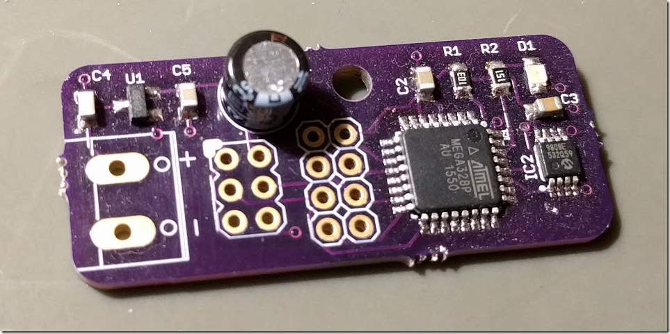
Here’s what the sensor module looks like when assembled (except for the radio):

image

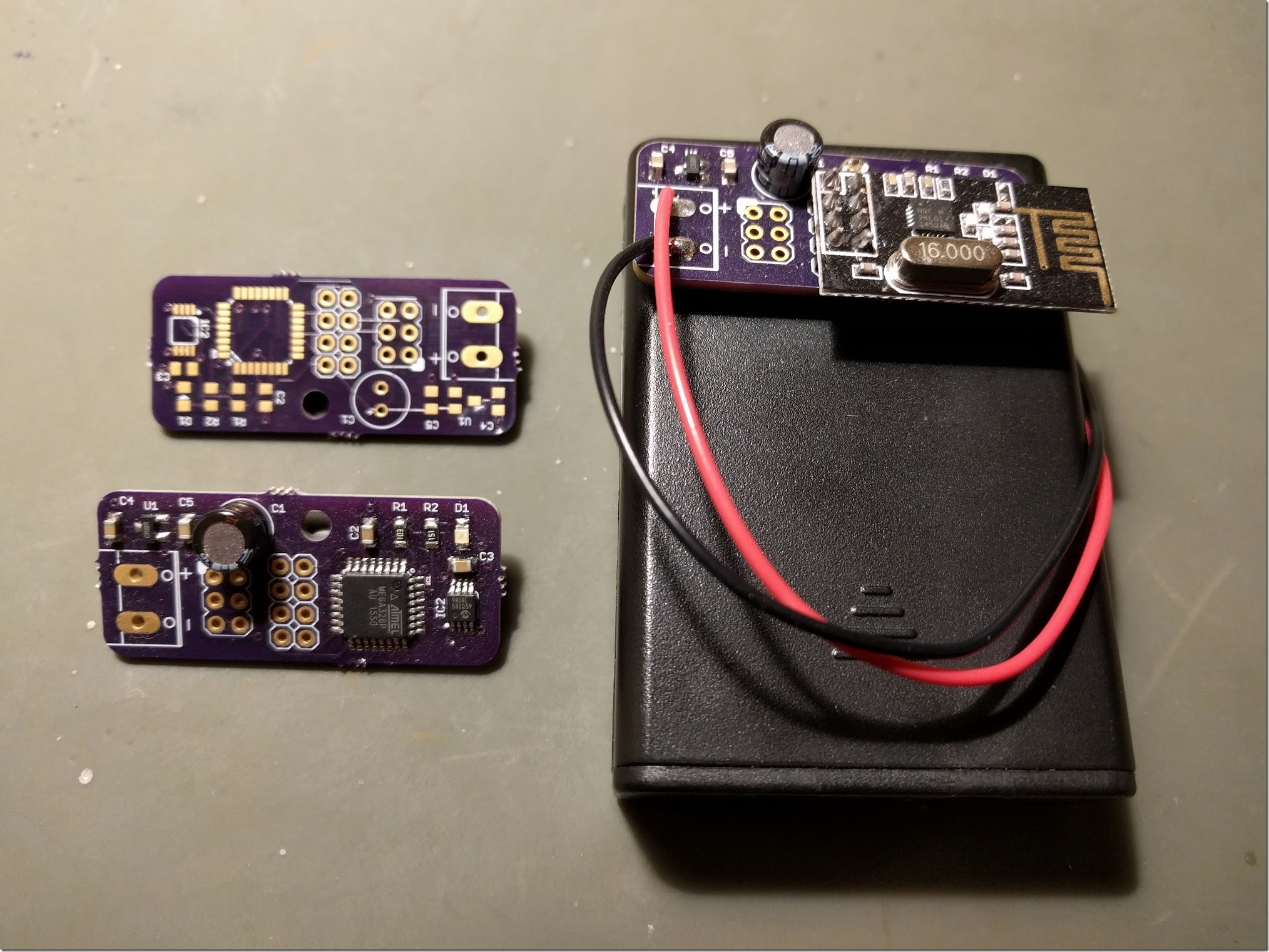
And here is a shot with a bare board, an assembled board minus radio, and an assembled board with radio and attached to a battery pack:

image

I2C timing

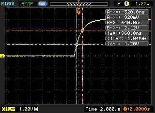
I mentioned earlier that I left out the usual external pull-up resistors on the I2C data lines, hoping that the ATMega328P internal pull-ups would be sufficient.  After I assembled and programmed a sensor board I double-checked the bus timing with my oscilloscope and it turned out that I bet correctly, just barely.  The I2C spec says that for a standard rate data bus (100 kbit/s), the maximum rise time must be 1µs or less, where rise time is defined as the time it takes to go from 0.3VDD to 0.7VDD.  In our case VDD is 3V, so we’re looking for the time it takes for the rising edge to go from just under 1V to just over 2V.  It turns out that we’re squeaking in just under the limit:

NewFile0

That’s good enough for my own personal use.  If I were designing a commercial product I would want a bigger margin of safety there.

Self-heating

When I tested the sensor module before adding low-power sleep modes to the software, I found that the processor would actually heat up the board a bit with its dissipated power and skew the temperature readings upward by about 0.5°C.  It’s not a big effect but it’s a noticeable error with the MCP9808 that I’m using.  At first I thought I would need to redesign the board to include isolation slots to better shield the temperature sensor device from the rest of the board, but then I found that adding low-power sleeps between sensor readings reduced power dissipation enough that any remaining skew was insignificant, so that crisis was averted.

Power consumption

I’ll save an in-depth discussion of low-power sleep modes for the post on the sensor module software, but here’s the general idea.  The software puts the processor, the radio, and the temperature sensor to sleep and sets a timer for eight seconds.  When the timer fires, the processor wakes up, wakes up the radio and temperature sensor, gets the current reading, and sends the data.  It then puts everything back to sleep for another eight seconds.

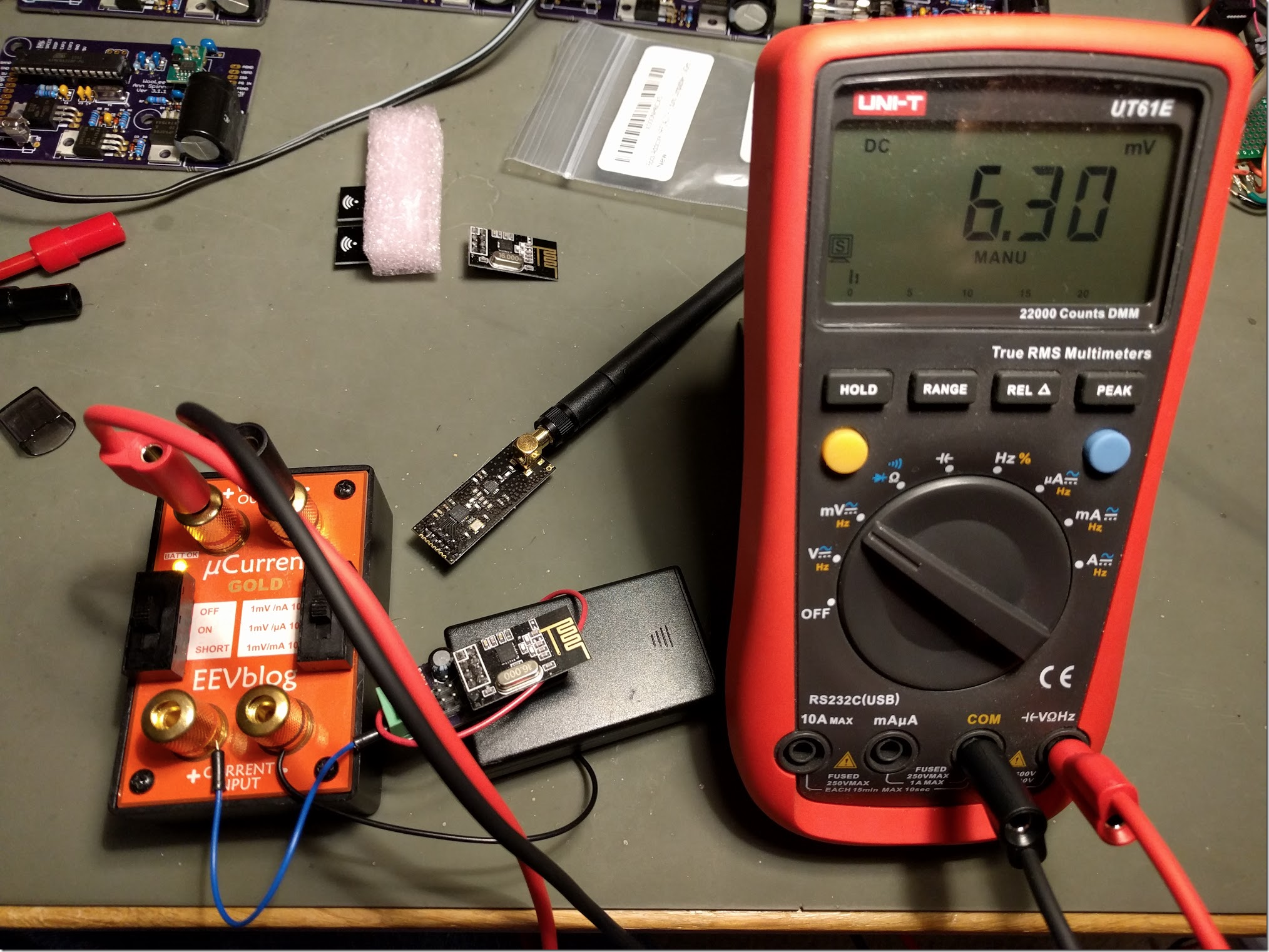
Here is the best result I was able to achieve during the eight-second sleep time (measured with an EEVBlog µCurrent):

image

The µCurrent was set to the µA range, so every µA of current across the input terminals produces 1 mV of voltage across the output terminals.  As you can see, I’m using 6.3 µA of current during sleep, which is great.

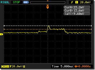
When the system wakes up to take a measurement and send data it uses more current, of course.  To characterize that transient behavior I hooked up the µCurrent to my oscilloscope.  I switched the µCurrent to the mA range, but the active current draw (and thus voltage signal) turned out to be right down in the noise for the oscilloscope.  I heavily filtered the signal and was able to get an idea of the duration (about 12 ms) and current draw (a quick spike to 23 mA then steady at ~14 mA for the rest of the wake period).

NewFile1

14 mA is a lot of current, relatively speaking, but the length of time we’re drawing that kind of current is quite short.  If I did my math right, it averages out to about an extra 1.5 µA over the course of an eight-second cycle, so our average current draw over time is approximately 8 µA.  The self-discharge rate of an AA battery is also roughly 8 uA so the life of our batteries is going to be 50% of what it would be if they were just sitting on a shelf, which is to say that the expected lifespan of these sensor modules is well over a year, at least.  We’ll see if it actually turns out that way in practice but I’ve had three sensor modules running continuously since March and their batteries are still going strong so things are on the right track.

Current measurement side notes

Characterizing current draw for a low-power device can be tricky because of the dynamic range of the current draw over time.  In my wireless sensor, the difference between the sleep state and the peak active state is three orders of magnitude (~3,650x).  The µCurrent is a great device but its measurement ranges cover nine orders of magnitude (1 nA to more than one amp) and compromises must be made.  The maximum voltage output of the µCurrent is 1.4V so you can measure up to about 1.4mA on the µA range for example (giving an output of 1.4V) then you have to switch to the mA range (giving an output of only 1.4mV).  A 1.4mV signal is going to be completely lost in noise on an oscilloscope so now you’re stuck in a very awkward position if you want to measure fast transients.  I don’t know of a great solution for this problem; maybe a secondary amplifier to boost the signal into a range that the oscilloscope is happy with?

Also, doing extremely low-current measurements is really tricky because external noise can easily swamp the signal you’re trying to measure even if it’s supposedly at a good level for your test instrument.  At the nA range, every test lead is an antenna pulling in all kinds of EMI and you have to be very careful how you set up your experiment.  It’s super-easy to get nothing but nonsense from your instrument if you do it wrong.

I think that’s all I wanted to cover for the sensor module hardware.  Next time we’ll talk about the software that makes it do useful stuff.

Building a wireless temperature sensor network, Part 1

Over the past few months I’ve been working on an electronics project that has taught me a lot.  Because I’ve benefited so much from the internet community in the process of my own learning, I’ll document the project here in hopes that it will help other people who want to learn.

This is part 1 of a series of blog posts documenting how I designed and built a multi-node wireless temperature sensor system.  Links to all of the posts in the series:

All hardware and software files for the project can be found in my GitHub repository.

The project

Because I’m a science geek, I’ve always thought it would be interesting to have a set of low-cost wireless temperature sensors that would allow me to monitor temperatures in a variety of locations around my property in real time, graph that data in real time, and hook up the output of certain sensors to physical display devices.  Of course you can purchase a wide variety of commercial wireless temperature sensors but they mostly have the drawback of being:

  • Expensive
  • Proprietary (not easy to log the collected data to the internet)
  • Not scalable to multiple sensor modules.

You can sometimes fix the last two problems by making the first problem worse (i.e. really expensive units often support internet data logging and many sensors) but I didn’t want to sink a lot of cash into this project, and anyway building my own is half the fun.

I thought about it off and on for quite a while and came up with this list of requirements:

  1. The overall system with one sensor module should cost less than $40 to build.
  2. The system should support at least 5 sensor modules.
  3. Each additional sensor module should cost less than $10 to build.
  4. The sensors should be wireless and battery powered so they can be placed anywhere.
  5. The battery life of the sensors should be at least one year.
  6. The sensors should be physically small so they can fit in tight spaces and are unobtrusive.
  7. There should be a central display device that shows the current reading of all sensors.  This display device doesn’t have to be battery powered (i.e. wall power will be available).
  8. The system should not require a PC or other expensive computing device.
  9. All sensor readings should be logged to my private Phant server on the internet.
  10. I should be able to tell when the battery on any sensor is getting low.

There might be a little retroactive tweaking of the requirements going on (since I’ve already mostly-finished the project) but that’s pretty much what I had in mind from the beginning.

General system design

Given those requirements, I started thinking about the general design of the system.

Base station

Working backwards, I knew that the logging repository for my collected data would be on the internet so I needed the system to be internet connected.  Of course I have a home WiFi network but WiFi is very power-intensive so the sensor modules can’t use it directly, therefore I needed a base station that was WiFi-capable and HTTP-capable.  It also needed to be inexpensive and to be able to drive some sort of display.  The display didn’t have to be anything fancy; a 16×2 character LCD screen would be sufficient for my purpose.

I’ve previously done a couple of other projects with the Particle Photon and it’s a great choice for this kind of problem.  It’s $20, it has a decent amount of memory and CPU resources, it supports WiFi, it has a great library for easy internet connectivity, and it has GPIO pins that allows me to hook up an LCD screen, a radio, buttons and anything else that I need for the base station.  I could have used a Raspberry Pi or Beaglebone Black for this purpose as well but they’re more expensive and have far more features than I really need for this project.  The Photon is the perfect balance of simplicity, power, and cost for a project like this.

Radios

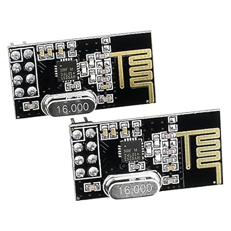
Ok, I have a base station.  How does it communicate with the sensor modules?  I needed a low-cost and low-power radio device that I could use to send small data packets.  There are lots of interesting products in this space, for example XBee, but they tend to be more expensive than I was hoping for.  I did a bit of research and discovered the nRF24L01+ chipset which is used by many very inexpensive radio modules available on Amazon and EBay.  There’s good software library support for this module on multiple platforms and it’s very easy to understand and use.  The range isn’t great, especially for the modules that use PCB-based antennas, but they’re pretty power-efficient and at a cost of just a dollar or two per radio, it’s hard to beat.  (Update: you can also buy versions of the nRF24L01+ radio that have an SMA antenna instead of a PCB antenna, which will significantly increase range.)

2pcs nRF24L01+ 2.4GHz Wireless Transceiver in Antistatic Foam Arduino Compatible

Side note: If you want to try using the nRF24L01+ radio on its own or prototype with it for your other projects, check out this breadboard adapter for the nRF24L01+ that I designed to make it easier to experiment with.  It separates the rows of pins so you can plug it into a breadboard and also includes an on-board 100uF capacitor and on-board 3.3V regulator so you can use it with a 5V device like the Arduino Uno.  The nRF24L01+ requires 3.3V power but is 5V tolerant on its I/O pins so you don’t need a level shifter.

Processor

Now we can turn our attention to the sensor modules themselves, which is the most interesting part of this project from an electronics perspective.  I didn’t find anything on the market that did exactly what I wanted to do so I decided to design my own sensors from scratch (which, again, is half the fun).

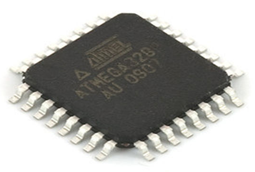
I’m pretty comfortable with the Arduino ecosystem and I’ve already done several projects using a bare ATMega328P chip which is the processor on an Arduino Uno.  The ATMega328P can be programmed to operate in a low-power mode that doesn’t draw much current and it has more than enough compute resources to drive the sensor module, since all it really needs to do is query a hardware temperature sensor device and then send that data to the radio module.  Also, it’s available in surface-mount packages that would allow me to minimize the size of the circuit board.

image

Temperature sensor

There are few commonly-used temperature sensors for hobbyists, including the TMP36 and the DS18B20, but there are other sensors on the market which have better resolution and accuracy ratings and since I was designing this thing from scratch, I figured I might as well go all the way so I chose the MCP9808 which has a typical accuracy of 0.25°C and a maximum resolution of 0.0625°C.  It’s not as popular in the hobby space because it’s only available in surface-mount packages, but I wanted to do an SMD board design for this project anyway and there are Arduino driver libraries that make communication easy.

Batteries and voltage regulator

I wanted the sensor modules to be able to run for a year or more on a single set of batteries because I’m lazy and don’t want to be changing batteries all the time.  That implied two things: a) I need to use batteries that have low self-discharge rates and b) the sensor board needs to be able to operate from the maximum voltage supplied by fresh batteries all the way down to the minimum voltage supplied by exhausted batteries.

I initially considered using a rechargeable LiPo battery but lithium batteries typically don’t have very good self-discharge rates.  That is, a typical LiPo battery will lose about 10% of its charge per month just sitting there while a modern rechargeable AA battery like the Enerloop brand will lose about 0.3% per month.  In addition, my sensors don’t have any high-current needs that LiPos are well-suited for, so rechargeable AAs definitely made the most sense.

Looking at the various components I had already picked out, each part had its own voltage operating range but everything seemed to overlap nicely in the 2.7V – 3V range.  AA batteries hit about 0.9V when they’re almost all the way drained, so three of them in series would allow me to use practically all of the energy in a set of batteries before shutting down.  However, a fresh AA cell can deliver up to 1.6V, or 4.8V for three of them in series, which is more than the absolute maximum voltage of the nRF24L01+ radio (3.6V).  So clearly we need a voltage regulator.

Now, we could just drop a basic 3.3V regulator like the LD1117V33 into the circuit but that device has a few major problems for our application.  One, it has a voltage drop of ~1.1V, which means that in order to supply 3.3V it has to be fed at least 4.4V, which means the batteries would have to be practically brand new.  Two, even if we did have enough source voltage range (maybe by adding more AA cells), the quiescent current of that device is around 5 mA.  That means that even if we’re drawing no current at all into the rest of the circuit, the regulator itself will burn 5 mA just sitting there, and there’s no way we’re going to last a year with that kind of power drain.

I did some research and found the MCP1700 which is great regulator for my particular application.  It can be ordered in a variety of low-power output voltages, including 3.0V which is what I want.  The quiescent current is only 1.8 µA, which is crazy low, and the dropout voltage at the tiny current levels we’re going to operating at is roughly 25mV or less, which is also crazy low. Finally, it’s available in a surface-mount SOT-23 package which is great.  This part can only deliver 250 mA of output current but we’re not going to draw anywhere near that anyway, so I don’t care.

Stay tuned

That’s enough words to start with!  In the next post I’ll go into detail on how I designed and built the sensor board.